¶ Welcome To Omnia
Omnia is a highly adaptable program designed to empower end users to effortlessly update their pump stations without requiring custom programming. Unlike traditional automation systems with rigid, predefined I/O configurations, Omnia offers dynamic I/O flexibility, enabling seamless adjustments as the station evolves. This will maximize the efficiency and performance of your pump system with ease.
We're continuously enhancing this dynamic program to better serve you, our valued customer. Your feedback is invaluable in helping us refine and improve both the program and its supporting manual. Please share your suggestions here, and thank you for your ongoing support!
¶ Omnia Updates
Stay informed about the latest Omnia updates! Check the end of this manual for details on when new program enhancements are released. Want to shape future updates? Submit your feature requests via the hyperlink below, and we’ll work to include them in the next Omnia update, ensuring your pump station remains cutting-edge.
¶ Older Omnia Program Versions
This software and its documentation are continuously updated. Panels that are not updated will run older software versions, and corresponding sections of this manual will document those legacy versions—what changed, why the change was made, and how the older behavior appears. As the program evolves, the manual expands accordingly, while maintaining support information for earlier releases to ensure continued compatibility and clarity.
¶ Main Operations
The control panel's operations and automations are fully tailored to the specific configuration of your pump station. While this manual covers all features within the Omnia program, not all may apply to your station's unique setup. Familiarize yourself with your pump station's components to better understand how the control panel and touchscreen interface drive its automation. For a concise overview of the touchscreen, refer to the link below.
¶ Screen Navigation
¶ Main Screen
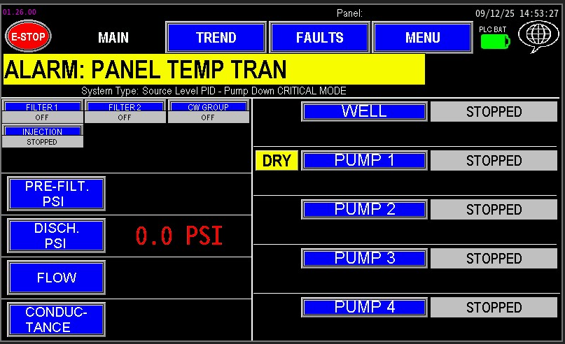
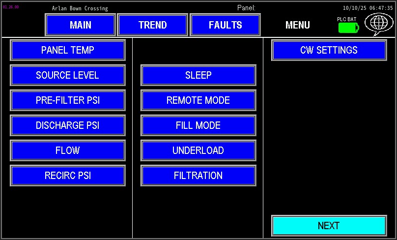
The main screen serves as the central hub for all operations, providing end users with a clear view of the pump station’s status, including its pumps and components. Mastering navigation of this screen is key to efficiently operating the system and making necessary adjustments. This section offers a basic overview of the information displayed. For detailed guidance on interpreting this data and operating the station, refer to this Omnia Manual.
As Omnia is a dynamic program, the main screen’s appearance varies depending on the configuration package purchased with your station, which determines the available options and data displayed. Note that Image 1.1 and all other images in this manual are for reference only and may not exactly match your setup.
Navigation Note: Any blue button on the main screens is a "Go To" button. Clicking these buttons will open a pop-up screen with settings related to the button’s label, allowing you to access and adjust specific features.
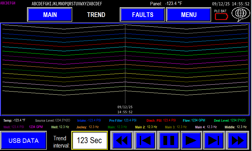
¶ Trend Screen
An analytical interface providing graphical representations of historical and real-time data, such as pressure, flow, and motor speed trends. This screen (image 1.2) enables operators to analyze system performance over time for optimization and troubleshooting.
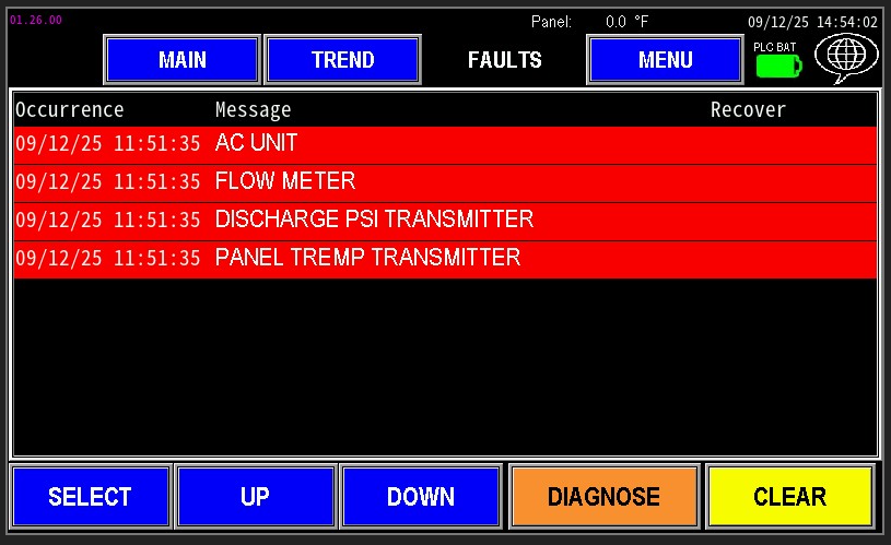
¶ Faults Screen
The fault screen (image1.3) displays the fault history and any current faults within the station. Faults are listed with timestamps, descriptions (e.g., high-pressure switch triggered, pump over-temperature), and severity levels, aiding in diagnostics and maintenance planning.
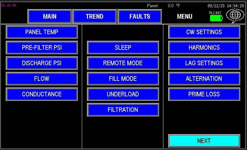
¶ Menu Screen
The Menu screen (image 1.4) provides access to pop-up configuration screens for all automation categories, including pump controls, VFD parameters, alarm settings, and system calibration. Each pop-up is designed for intuitive navigation and precise adjustments.
¶ Pumps
This section provides comprehensive details on configuring any pump within the automation system. While some settings are consistent across different pumps, each pump may respond uniquely. To ensure proper setup, familiarize yourself with your specific pump station and its controls before making adjustments. Review this manual thoroughly to understand the station’s components and settings for optimal configuration.
These common pump settings are specific to the individual pump that is being adjusted, but the process is the same when adjusting these settings from one pump to the next. When referencing these settings in any pump, reference these links.
¶ Sleep Settings
Sleep settings define when the pump station reduces or stops operation during low‑demand periods to conserve energy, minimize wear, and preserve system stability. They monitor station setpoint conditions to recognize low demand and pause pumps until demand resumes. For detailed configuration and guidance, see the linked documentation.
¶ Overcycle
An overcycle occurs when a pump starts and stops too frequently within a short period. Excessive cycling increases mechanical and electrical wear, shortens component life (seals, bearings, starters, VFDs), and can cause pressure/flow instability. For detailed configuration and guidance, see the linked documentation.
¶ Permissive
Permissive indicates whether a pump is authorized to start. The Permissive screen shows the start sequence and the PLC conditions required for the pump to run, making it an effective diagnostic tool for identifying why a pump won’t start even when other indicators appear normal.
¶ Harmonic Filter
A harmonic filter reduces electrical distortion (harmonics) caused by devices like VFDs and rectifiers. By filtering out unwanted frequencies, it protects equipment from overheating, reduces power losses, prevents nuisance trips, and improves overall power quality.
¶ Underload
Underload: a condition where a pump or motor is running below its expected or required load. Causes reduced efficiency, possible overheating of bearings, poor lubrication, increased vibration, and can indicate a clogged suction, closed valves, broken coupling, or incorrect system sizing.
¶ Injector Pump
¶ Jockey Pump
¶ Main Pump
¶ Intermediate Pump
¶ Primer Pump
¶ Recirc Pump
Well Pump
¶ Sensors
Sensors give a pump station the measurements it needs to run safely and efficiently.
- Pressure sensors: measure intake/discharge pressure. Used to control pump speed, start/stop pumps, detect leaks or overpressure, and protect equipment.
- Level sensors (and floats): measure tank or sump water levels. Used to start/stop fills, prevent dry‑run or overfill, and enable level‑based control.
- Flow sensors: measure water flow rate and totals. Used for flow control, leak detection, reporting, and validating filter/flush operations.
Together (along with other types of sensors) they provide the feedback the controller uses for automation, protection, and reporting.
¶ Pressure Transmitters
List of Pressure Transmitters Utilized in the Omnia Program
- Discharge Pressure Transmitter
- Intake Pressure Transmitter
- Pre-Filter Pressure Transmitter
- Pre-WYE Pressure Transmitter
- Recirc Pressure Transmitter
- Well Pressure Transmitter
¶ Flow Meters
List of Flow Meters utilized in the Omnia Program
- Fill Flow Meter
- Filter Flow Meter
- Injector Flow Meter
- Leak Flow Meter
- Recirc Flow Meter
- Station Flow Meter
- Well Flow Meter
¶ Level Transmitters
List of Level Transmitters utilized in the Omnia Program
¶ Misc Transmitter Sensors
Additional Transmitter or Sensors that are utilized in the Omnia Program
¶ Station Valves
List of Station Valves that the Omnia program supports
¶ CW Valves
A CW (Clean Water) valve directs clean water back into the pump intake to flush and clean the intake screen or strainer. It protects pumps by removing debris buildup and is typically operated automatically during pump runs or via manual/test controls.
¶ Filtration and Filter Flush Valve
A filter flush valve opens to flush trapped debris from a filter element or screen. Activated automatically or manually during a cleaning cycle, it directs high‑velocity flow to remove contaminants and restore filter performance
¶ Prime Assure Valve
A Prime Assure valve maintains or restores pump prime by allowing controlled water flow into the pump suction via the discharge. It prevents air intrusion, supports automatic priming sequences, and helps ensure reliable startup and continuous pump operation.
¶ Injection Valves
An injection valve controls the delivery of chemicals into the water line. It opens and closes (or modulates) in coordination with the injector pump to ensure accurate dosing, prevent air pockets, and maintain consistent chemical concentration in the system.
¶ Scrubber Valve
A scrubber valve directs chemical‑enhanced wash water or injector flow onto a screen or surface to dislodge stubborn deposits. Operated with the injection pump, it provides targeted cleaning action (scrubbing) to improve filter/intake cleaning effectiveness beyond standard flushing.
¶ Master Valve
A master valve is typically used on a booster pump system as the primary electronically actuated shutoff valve. In the event of a line break or similar fault condition, it can stop water flow to help prevent significant water loss.
¶ Menu Screens
Being familiar with the HMI interface—including which screens are accessible from both the menu base and the main screen—can significantly improve troubleshooting efficiency. Quick navigation allows operators to quickly identify and resolve issues, minimizing station downtime. Familiarity with station components and their locations on the screens helps in diagnosing malfunctions swiftly and ensures smooth, continuous operation.
The menu screen also works dynamically like all other screens on the HMI. It reads the configuration of the I/O page and places the links to the pages needed to run the pump station. Image 1.1 and 1.2 show how different a page can look from one configuration to the next.
|
|
Navigate the List below to find which screen you are wanting to learn about:
¶ Menu Screen 1
These settings pertain to Menu Screen 1.
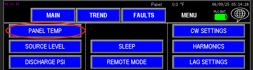
¶ Panel Temperature Settings
Monitoring panel temperature is essential to maintain reliable operation of electrical components (image 1.1). Extreme heat or cold accelerates component degradation and can cause malfunctions that affect communications and overall panel performance.
¶ Injection Flow
The Injection Flow Settings pertain to the operation of the injector pump and its associated system.
¶ Fill Flow
Fill flow settings pertain to the system section controlled by the fill device.
¶ Pre-Filter PSI
Stations with a water filter require additional monitoring to maintain reliable operation. A Pre‑Filter transmitter measures the pressure upstream of the filter.
¶ Well PSI
The Well Pressure settings govern the pressure used specifically for controlling the well pump. These settings are independent of the station’s other pressure transmitters and affect only well‑pump operation.
¶ Well Flow
The well flow meter monitors the total volume of water pumped by the well pump.
¶ Destination Level
These settings pertain to the tank or pond being filled by the pump station. They help the system determine when water demand is active — when the water level drops below a set point — and when demand has decreased — when the level reaches a specified upper limit. This allows the station to operate efficiently, filling only as needed based on the target water levels.
¶ Source Level
The source level transmitter measures the level of the water supply feeding the pump station. These settings configure the transmitter to ensure accurate level detection and include protection parameters to prevent damage to the pumps. Proper setup helps maintain reliable operation and safeguards the system from operating under low or excessive water levels.
¶ Intake PSI
Intake pressure settings monitor the pressure feeding the station inlet. The intake source may be a gravity-fed tank or pond, or the discharge from another station.
¶ Discharge PSI
Discharge pressure is the primary control parameter for most station operations in Omnia. The automation system monitors the discharge pressure transmitter and adjusts pump operation to maintain the required pressure setpoint for the application.
¶ Flow
The station flow meter monitors the total volume of water passing through the main discharge line.
¶ Filter Flow
The filter flow meter monitors the volume of water used to flush the filter.
¶ pH
A pH sensor measures the acidity or alkalinity of water, providing critical data for applications where water quality is essential for safety and system performance.
¶ Conductance
The conductivity meter measures the minerals and dissolved solids in water by assessing its electrical conductance.
¶ Enclosure Temp
When a pump station is housed within an enclosure, such as a pump house or metal box, monitoring the internal temperature is essential to ensure proper operation and prevent electrical failure.
¶ Recirc PSI
Recirc Pressure settings govern the pressure used specifically for controlling the speed of the Recirc pump.
¶ Recirc Flow
The Recirc flow meter monitors the total flow of water circulating through the Recirc Pump line.
¶ Leak Flow
Leak flow meters are used on pump stations with primer or suction lift pumps. They monitor the total flow of water recirculating back into the intake side of the pumps, which helps keep the intake system primed.
¶ Well Level
The well level transmitter measures the water level in the sump or supply source for the well pump.
¶ Pre-WYE PSI
Pre -WYE PSI is monitoring the inlet side of a WYE strainer, whether the strainer is configured on the intake, or discharge side of the pumps.
¶ Sleep Settings
See the pump settings section above, or click on the link below:
¶ Remote Mode
Remote Mode allows an external controller or system to start and stop the pump station, overriding the panel automation and scheduler.
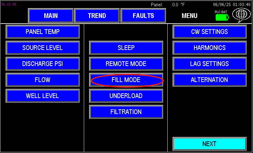
¶ Fill Mode
When stations start up for the first time or after a power outage, line pressure may be extremely low. Rapidly ramping pump speeds to meet the normal pressure setpoint can stress downstream valves and components, potentially causing damage or delays for repairs. This is where Fill Mode comes into play
¶ Underload
Underload: a condition where a pump or motor is running below its expected or required load. Causes reduced efficiency, possible overheating of bearings, poor lubrication, increased vibration, and can indicate a clogged suction, closed valves, broken coupling, or incorrect system sizing.
¶ Filtration and Filter Flush Valve
A filter flush valve opens to flush trapped debris from a filter element or screen. Activated automatically or manually during a cleaning cycle, it directs high‑velocity flow to remove contaminants and restore filter performance
¶ CW Valves
A CW (Clean Water) valve directs clean water back into the pump intake to flush and clean the intake screen or strainer. It protects pumps by removing debris buildup and is typically operated automatically during pump runs or via manual/test controls.
¶ Harmonic Filter
A harmonic filter reduces electrical distortion (harmonics) caused by devices like VFDs and rectifiers. By filtering out unwanted frequencies, it protects equipment from overheating, reduces power losses, prevents nuisance trips, and improves overall power quality.
¶ Lag Settings
Lag Pumps are the main pumps that activate after the lead main pump is running but unable to meet the station’s water demand. The Lag Settings determine when the Lag pump needs to start and stop, based on how the lead pump is performing.
¶ Alternation
The Alternation function enables the main pumps to rotate the role of the Lead Pump, which operates the longest during a watering cycle.
¶ Prime Loss
Prime Loss applies to stations with a suction‑lift intake. It monitors whether pumps retain water in the volutes while the station is idle. This feature requires a wet/dry switch. If the wet switch indicates dry (or the pumps lose prime), the station will return to priming mode.
¶ Primer Pump
A primer pump is a small auxiliary pump that fills the suction line and pump volute with water so the main pump can start without drawing air, preventing dry‑run damage. Navigate to the pump section or click the link below to get to the primer pump settings.
¶ Fill Valve
A fill valve is a discharge valve used to divert water from the pump station to fill a reservoir—such as a pond, sump, or tank—on demand.
¶ Menu Screen 2
¶ PID Settings
PID is a control algorithm used to maintain a system at its desired setpoint by continuously adjusting the output to react to real-time conditions. When controlling motors via VFDs, PID enables smooth and precise regulation of pump speed based on parameters such as pressure, flow, or level.
¶ PID Trim
PID Trim monitors source water level to protect pumps from running dry. This mode slows the pump speeds by trimming the setpoint of the station when low water supply conditions are active.
¶ I/O Status
The IO Status screen displays real-time data on all inputs, outputs, and analog signals within the station. It provides an at-a-glance view of current sensor readings, valve statuses, relay states, and signal values. This makes it an invaluable tool for troubleshooting, verifying proper operation, and observing how the station responds to various conditions.
¶ Scheduler
The scheduler functions like a standard irrigation controller but is integrated into Omnia for easier setup and management. Use it to automate station run times and restrict operation during specified times of day. Configure schedules, enable/disable events, and set time windows so the station only runs when permitted.
¶ Rain Settings
If the area served by the pump station receives rainfall, rain sensor settings can prevent unnecessary watering, reduce costs, and help avoid overwatering or flooding after heavy rain.
¶ Reports
The Reports tab tracks water usage through the station for operational monitoring or regulatory reporting. It displays daily totals and historical data for previous days, making it easy to review consumption trends. Report data can be exported or emailed to stakeholders as needed.
¶ Motor CT
The Motor CT monitors the motor or VFD current draw during pump operation, providing real‑time amperage data for monitoring, fault detection, and performance analysis.
¶ Self Prime
Self‑Prime Settings configure the pump station for self‑priming pumps (e.g., certain centrifugal or diaphragm models). These pumps require a defined priming period before water reaches the pump head and is discharged.
¶ Password Protection
To prevent unauthorized changes while the station is unattended, configure a password under the Password tab. Enabling a password locks access to HMI screens and settings, protecting the system from inadvertent or incorrect adjustments by untrained personnel.
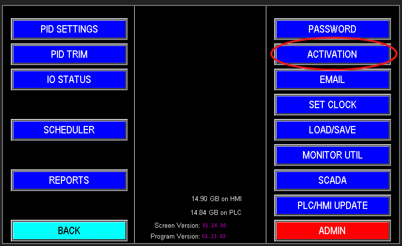
¶ Activation
The Activation tab (image 1.1) should only be used by authorized personal. If the panel is no longer in demo mode, and activation is required, contact PPS for more information.
¶ Emails
The Omnia program can automatically send email or text alerts to operators when a station shuts down, including the reason for the shutdown.
¶ Set Clock
To edit the system time and date, select "Set Clock" to open the clock setup screen. All emails, records, and event timestamps use this HMI time — ensure the date and time are set correctly.
¶ Load/Save
The Load/Save screen is a crucial tool for operators, allowing them to save the optimal configuration of the station when it is performing at peak efficiency. This feature provides a straightforward way to store all current settings and configurations, enabling quick restoration if the station’s performance begins to decline.
¶ Monitor Utilities
Monitor Utilities is access to the configuration of the HMI screen. Allows access to language settings, IP address, and many other screen behavioral settings. Access to this is password protected and would need to be access via someone authorized to access it.
- More information coming soon
¶ PLC/HMI Update
The PLC/HMI Update feature allows authorized personnel to upgrade station automation to the latest available software and HMI releases. Access is password‑protected and should be performed only by trained or authorized staff.
¶ Admin
Password protected settings for Authorized Personnel only.
¶ SCADA
SCADA provides communication and supervisory control across distributed controllers and sites. It enables controllers to share status and process data so systems that depend on remote inputs can operate correctly.
¶ Admin Use Only
The Admin Manual supplements this guide. It contains detailed instructions for authorized personnel to configure and maintain administrative settings. If you are not authorized, contact PPS for support—changes made in the admin area can significantly affect station automation and may damage equipment if applied incorrectly.
¶ Service and Troubleshooting
For automation issues, consult the Fault Screen first to identify the fault and begin diagnosis. The Diagnostics tab provides detailed information useful for troubleshooting automation problems and locating corrective actions. Use this manual as your primary troubleshooting resource to track faults, identify likely causes, and follow recommended remedies. If the issue cannot be resolved promptly, contact PPS Service for further assistance.
¶ Trend Screen
The Trend Screen serves as the central data management hub for the pump station, providing comprehensive access to both real-time and historical operational data.
¶ Fault Screen
The Fault Screen provides a comprehensive historical record of faults that have occurred within the pump station, enabling operators to track, analyze, and resolve issues effectively. This section is designed to assist in diagnosing system problems by organizing fault data into distinct categories and offering navigation and diagnostic tools.
¶ System Architecture
This section is for all the different automation build plans that are supported by the Omnia Prgram. Scroll through the list to determine which program design is right for you.
¶ Omnia Program Version Updates
Have an older version of Omnia, or curious on how the program has grown since it's inception? Scroll through the different versions here and see what has changed over the years.