¶ Well Flow Meter
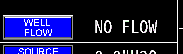
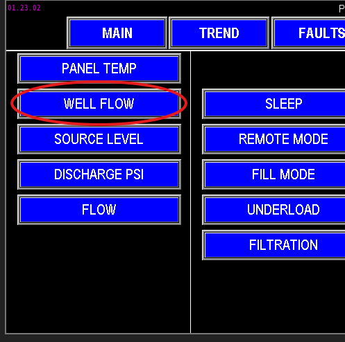
The well flow meter monitors the total volume of water pumped by the well. To view or configure this flow meter, access the settings via the Main screen (Image 1.1) or the menu screen (Image 1.2).
See Well Pump for settings pertaining to the pump:
|
|
¶ Flow settings
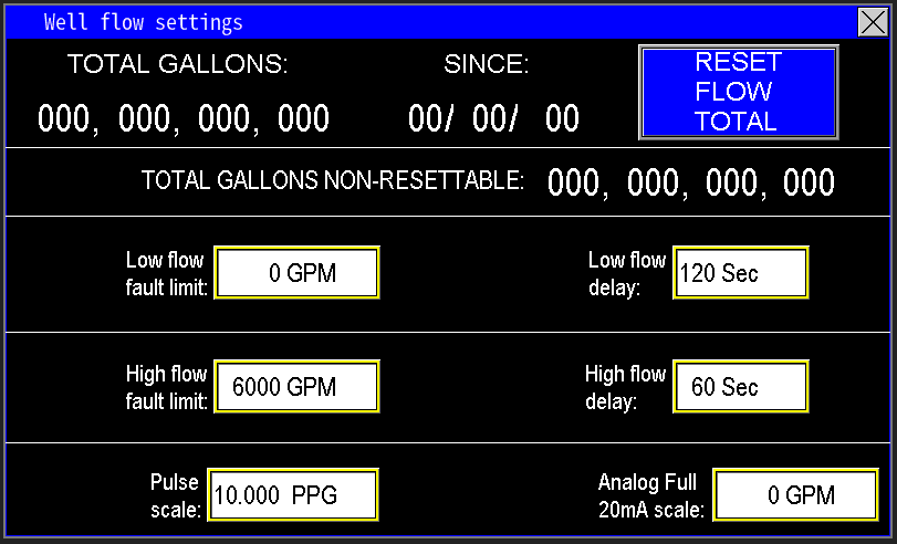
The values entered in the well flow settings are the parameters that the PLC will use to monitor and control the well pump operation (image 1.3). These settings ensure accurate flow measurement and proper system response based on the well's flow conditions.
¶ Well Flow Data
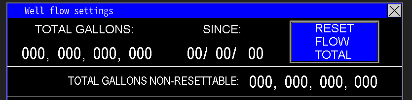
At the top of the screen (image 1.4), the PLC displays the total gallons measured by the well flow meter, representing the cumulative volume pumped by the well. The “since” date reflects the last time the total was reset; pressing the “Reset Flow Total” button will reset this value to zero and update the “since” date to the current date set on the HMI.
Additionally, the Total Gallons Non-Resettable totalizer continually records the total volume of water pumped by the well over its entire operational lifetime. This value cannot be reset and provides a permanent record of total well output.
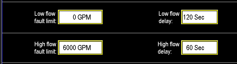
¶ Low and High Flow fault limits and delays
The low and high flow limits (Image 1.5) serve as diagnostic thresholds to alert the PLC of potential issues with the well pump system, allowing preventive action before damage occurs. Both limits monitor flow in GPM and include a timer delay to avoid false alarms.
Low Flow Fault: The system will only fault and shut down the well pump if the flow remains at 0 GPM for at least 120 seconds. Until then, the pump continues to operate despite low flow conditions.
High Flow Fault: The system will fault and stop the station if the flow exceeds 6000 GPM continuously for 60 seconds. After this delay, the station will stop in order to prevent any damage from excessive flow.
These thresholds help ensure safe and reliable pump operation by detecting abnormal flow conditions and responding accordingly.
¶ Pulse Scale and Analog Full 20mA scale
Omnia supports monitoring station, fill, recirc, and well flow meters that output pulse or analog mA signals. For pulse meters, follow the manufacturer's instructions to determine the flow meter’s k‑factor (pulses per gallon). Enter this value into the Pulse Scale setting.
Next, zero the mA Scale—this activates the pulse measurement mode. If the mA scale is not zeroed, pulse readings will not function correctly. Once configured, the system converts incoming pulses into flow rates, displaying the flow in GPM on the main screen of the HMI (Image 1.6).
The Analog Full 20mA Scale should be set to match the maximum flow rating of the flow meter’s 20mA output. This value typically represents the highest flow the meter is rated to measure. For meters with adjustable 20mA span, verify that this scale matches the configured maximum output value on the flow meter to ensure accurate readings and proper system calibration.