¶ Well Pump
Common pump settings that apply to the Jockey, Intermediate, Main, and Well pumps are found here:
Well Pumps integrated into pump stations are classified as part of the main pumps. They typically supply water to a tank or directly to the intake of the main pump station for watering cycles. The automation of well pumps varies based on the station’s configuration, with multiple setups possible. Below, we outline the different configurations and their respective automation settings.
¶ Well Pump PID Configurations
When purchasing a pump station equipped with a well pump, it’s critical to understand the PID Process Variables that the well pump can be configured to follow within the Omnia program. The available process variables depend on the station’s design and are set during the initial configuration by PPS. If changes are made to the scope of the Well pump, this will need to be reconfigured by PPS.
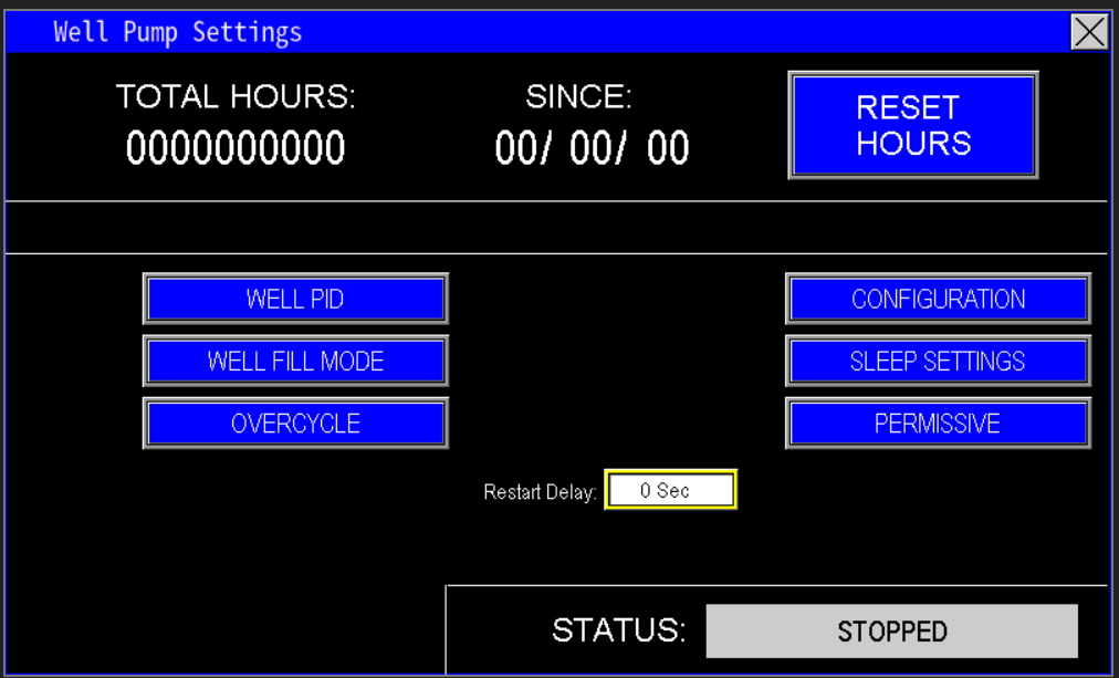
¶ Well Pump Settings
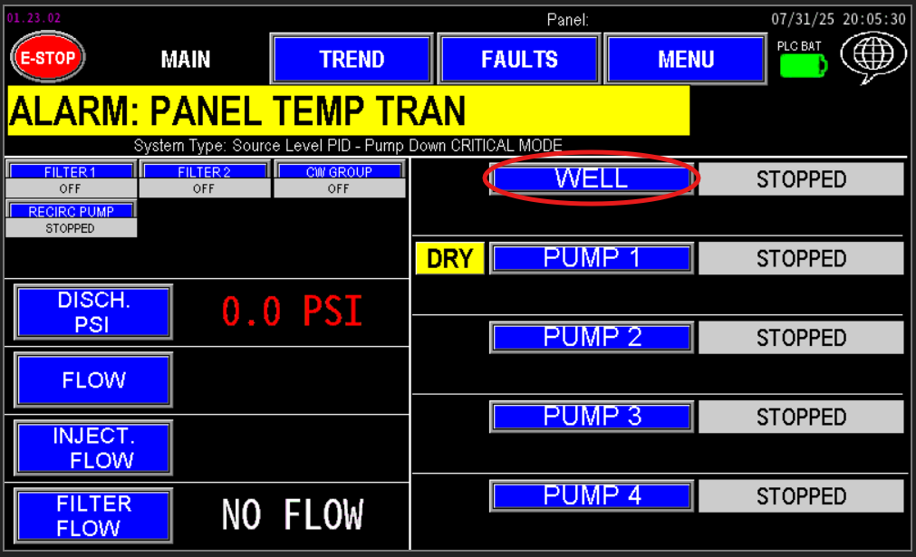
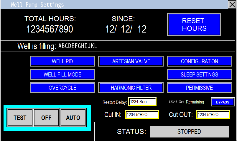
To access the well pump settings (image 1.1), enter through the main screen (image 1.2). From here all the settings to run the well pump are here. Each application will be different depending on the well configuration.
|
|
¶ Well Pump Data
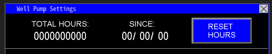
The section of the screen (Image 1.3) displays the Total Hours the well pump or motor has been running, accumulating time during operation. If the pump or motor is replaced due to a breakdown, pressing the Reset Hours button will reset the Total Hours to zero and update the Since date to the current date.. This feature provides an effective way to track the operational lifespan of each pump or motor.
¶ Well PID
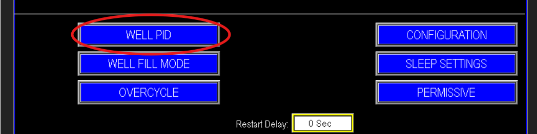
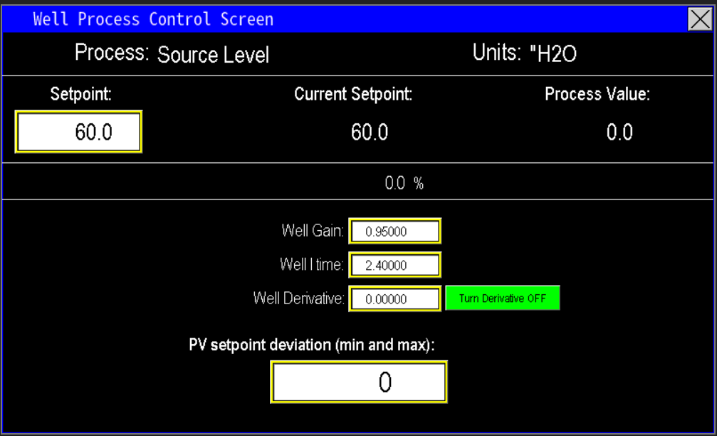
The Well PID Button (Image 1.4) provides access to the Well Process Control Screen (Image 1.5), where the well pump’s operation is managed based on the configured Process Variable (e.g., pressure, flow, level, or PID output). The settings displayed on this screen depend on the station’s initial configuration, set at the factory. If you need to change the process variable, contact PPS for assistance with reconfiguration.
|
|
¶ Process variable and setpoint
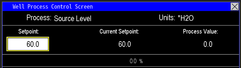
At the top of the Well Process Control Screen (Image 1.6), the selected Process Variable for the Well pump is displayed. In this example, the Well pump is configured to follow the Source Level of the main pump station, meaning it operates to maintain the water level in the source tank.
- Units: The units of measurement for the setpoint are shown. In this case, the setpoint is 60 inches of water, indicating the target level the well pump is working to achieve.
- Current Setpoint: This reflects the setpoint the well pump is currently targeting, which may align with the configured 60" in this example.
- Process Value: This displays the current measured value of the process variable (e.g., the actual water level in inches), though the specific value is not provided in the example.
- PID Output %: This percentage indicates the output signal the PLC is sending to the variable frequency drive (VFD) to control the pump’s speed, ensuring it aligns with the setpoint.
The units and settings will vary based on the process variable selected during the station’s configuration (e.g., pressure in PSI, flow in GPM, or level in inches). If a different process variable is needed, contact PPS for assistance with reconfiguration.
¶ PID Adjustments
The PID Adjustment Values on the Well Process Control Screen (Image 1.5) enable fine-tuning of the well pump’s response to the selected process variable (e.g., source level, pressure, or flow). This is achieved by adjusting the following parameters:
- Gain: Controls the proportional response, determining how aggressively the pump adjusts to deviations from the setpoint.
- I Time (Integral Time): Adjusts the time taken to correct steady-state errors, ensuring the pump reaches and maintains the setpoint.
- Derivative (if applicable): Smooths out rapid changes in the process variable, reducing overshooting or oscillations, though this is optional and used as needed.
These adjustments should only be made by personnel experienced with PID tuning to avoid instability or inefficient pump operation. Improper settings can lead to issues like excessive cycling or failure to maintain the setpoint.
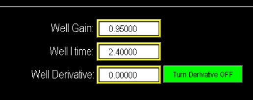
¶ Gain
The Gain setting (Image 1.7) adjusts the well pump’s output in proportion to the Offset, which is the difference between the current Process Variable (e.g., source level, pressure, or flow) and the desired Setpoint. Proper tuning of the Gain is critical for balancing responsiveness and stability:
- Low Gain: Reduces overshooting and undershooting, allowing the PLC to maintain the process variable closer to the setpoint with minimal oscillation. However, this results in a slower response time to reach the setpoint.
- High Gain: Speeds up the process variable’s approach to the setpoint, but increases oscillation. If set too high, the variable frequency drive (VFD) may cause the motor to rapidly speed up and slow down, leading to unstable operation and excessive oscillations.
- Balancing Gain: Setting the Gain too low can cause sluggish response, leading to dips or spikes in the process variable. Conversely, setting it too high can result in erratic motor behavior due to overly rapid reactions to changes in the process variable.
Adjusting the Gain should be done carefully by personnel experienced with PID tuning to ensure smooth and efficient pump operation.
¶ Integration
The Integration (I Time) setting on the Well Process Control Screen (Image 1.5) determines how quickly the system applies corrections to eliminate the Offset—the difference between the current Process Variable (e.g., source level, pressure, or flow) and the Setpoint. When the Gain is properly set and the system is stable, there may still be a small offset from the setpoint. The I Time helps fine-tune the system to minimize this offset and bring the process variable closer to the setpoint (zero offset).
- High I Time (Faster Integration): Increasing the I Time causes the program to correct the offset more quickly, driving the process variable toward the setpoint faster. However, if set too high, this can lead to overshooting or undershooting, causing instability or oscillations in the system.
- Low I Time (Slower Integration): Decreasing the I Time slows the correction process, taking longer to reduce the offset and reach the setpoint. While this reduces the risk of overshooting, it may result in prolonged deviations from the setpoint.
- Balancing I Time: The I Time controls the speed at which the PLC applies corrections to the process variable. Proper adjustment ensures smooth convergence to the setpoint without excessive oscillations or delays.
Adjusting the I Time requires expertise in PID tuning to avoid destabilizing the system. It should be done by personnel familiar with these settings to achieve optimal performance.
¶ Derivative
The Derivative setting on the Well Process Control Screen (Image 1.5) governs how the Omnia program responds to rapid changes in the Process Variable (e.g., source level, pressure, or flow). It is particularly useful for stabilizing the pump station during sudden, external events that cause significant fluctuations in the process variable.
- High Derivative: Increasing the Derivative value enhances the system’s response to dramatic changes, allowing the pump station to recover to the Setpoint more quickly. This can help stabilize the system during abrupt events but may lead to overcorrections if set too high.
- Low Derivative: Decreasing the Derivative value slows the system’s response to rapid changes, resulting in a more gradual recovery to the setpoint. This reduces the risk of overcorrections but may delay stabilization.
- Balancing Derivative: The Derivative setting is optional and typically used when fine-tuning is needed beyond Gain and I Time (Integration) adjustments. In most cases, proper configuration of Gain and I Time (as described in previous sections) can adequately stabilize the process, making Derivative adjustments less critical.
Adjusting the Derivative should be performed by personnel experienced with PID tuning to avoid instability, such as excessive oscillations or sluggish responses.
¶ PV Setpoint Deviation (min and max)
The PV Setpoint Deviation setting on the Well Process Control Screen (Image 1.5) allows users to fine-tune the sensitivity of the well pump’s response to deviations from the Process Variable (PV) setpoint (e.g., source level, pressure, or flow). This setting adjusts the operational scope of the PLC, influencing how aggressively or conservatively the system reacts to changes in the process variable.
- Lower PV Setpoint Deviation: A smaller value makes the PLC focus more precisely on the setpoint, increasing the system’s reactivity. This causes the pump to respond quickly to even minor deviations, which is ideal for systems requiring tight control but may lead to overcorrections or oscillations if set too low.
- Higher PV Setpoint Deviation: A larger value widens the PLC’s acceptable range around the setpoint, making the system less reactive and slowing down response times to changes. This can stabilize the system by reducing rapid adjustments but may delay corrections if set too high.
- Customization for Station Variability: Given the diverse configurations and builds of pump stations, the ability to adjust the PV Setpoint Deviation ensures that the PLC’s response can be tailored to the specific needs of any station. This flexibility allows for precise calibration to optimize performance and stability.
Adjusting the PV Setpoint Deviation should be done by personnel familiar with the station’s operation and PID tuning to avoid issues like excessive cycling or sluggish performance.
¶ Well Fill Mode
The Well Fill Mode (Image 1.8) is designed for Well pumps that supply water directly to the main line. In this mode, the PLC scales the ell pump’s speed based on the selected Process Variable (e.g., pressure, flow, or level) to maintain continuous water movement at a reduced rate, rather than shutting off the pump or faulting the station. This helps ensure smooth operation and prevents damaging components in the discharge line from sudden spikes in pressure.
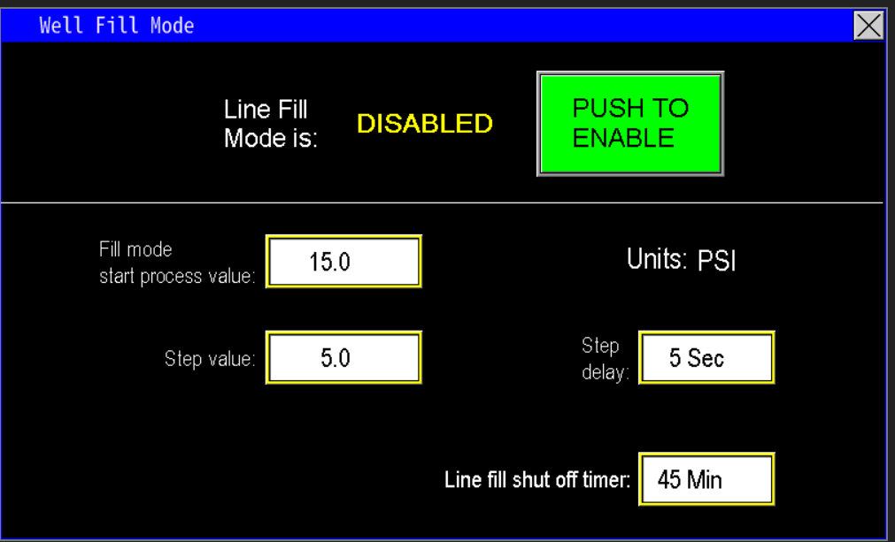
¶ Fill Mode start process
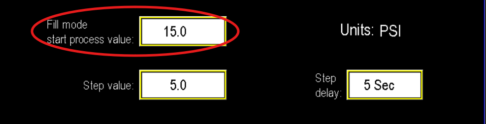
When Well Fill Mode is Enabled (Image 1.8), the PLC will gather information from the Process Variable value, shown with its units on the screen (Image 1.9). If the process value from the transmitter is below the Fill Mode Start Process Value at start up (Image 2.0), the Well pump enters Fill Mode.
In the example given, if the pressure in the well’s discharge starts falls below the Start Setpoint of 15 PSI, the PLC activates Well Fill Mode. In this mode, the PLC adjusts the well pump’s setpoint to a temporary value based on the starting process variable (15 PSI in this case) and modulates the pump’s speed to maintain this new setpoint. The PLC will hold this temporary setpoint until the next operational step is triggered, ensuring continuous water flow at a reduced rate to prevent the pump from shutting off or faulting the station.

|
|
¶ Step Value and Delay
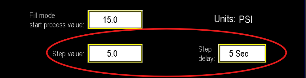
The Step Value and Delay parameters determine how quickly the well pump increments the station’s pressure setpoint. In the example below (Image 2.1), the pump increases the setpoint by 5 psi per step. For instance, if the initial setpoint is 15 psi, the first step raises it to 20 psi. After the pump reaches and holds 20 psi for 5 seconds, it advances to the next step (25 psi). This pattern continues until the fill mode setpoint equals the well pump’s original setpoint. At that time, the pump exits fill mode and returns to normal operation.
¶ Line fill shut off timer
This timer (image 2.2) sets the maximum duration for which Fill Mode remains active. Estimate the time required for the line to reach normal operating pressure and set the timer accordingly. If the line does not reach setpoint within this period, the station will fault, indicating the pump cannot achieve the required pressure.
In the example below, a 45-minute timeout will stop the pump if it fails to fill the line within that interval. Possible causes include pump malfunction, too many open zones, an open valve, or a ruptured pipe preventing pressure buildup.

¶ Artesian Valve
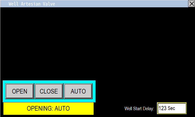
When the well is configured with an Artesian Valve, a popup control button appears. This screen functions as a virtual HOA (Hand-Off-Auto) for the valve:
- OPEN — manually opens the valve
- CLOSE — manually closes the valve
- AUTO — allows the PLC’s automation to control the valve
¶ Well Start Delay
The Well Start Delay sets how long the Artesian Valve remains open (per the value entered) before the well pump starts. This delay reduces well pressure to facilitate pump startup (image 2.3).
¶ Configuration
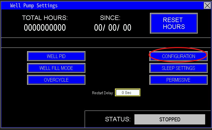
The Well Configuration button opens additional well pump settings (Image 2.4). Available options depend on the factory configuration of the pump station; some features may be present while others are not.
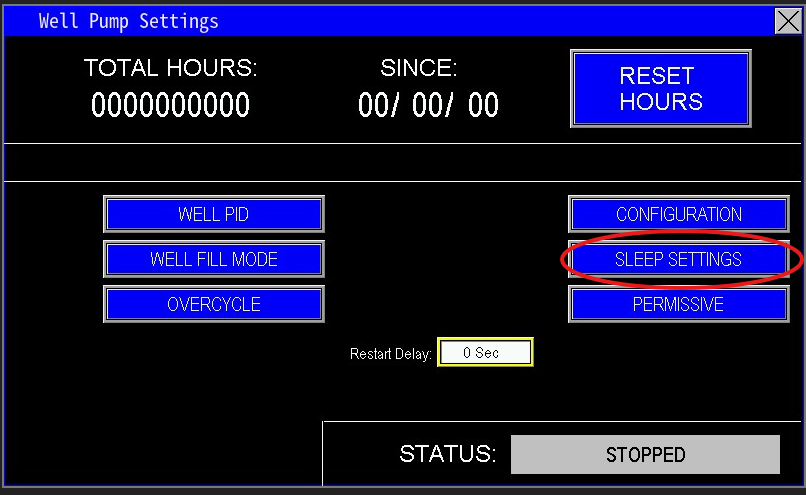
If the station is configured with a virtual HOA, the HOA control will appear in the lower-left corner of the Well Settings screen (Image 2.5).
|
|
¶ Well Configuration Screen
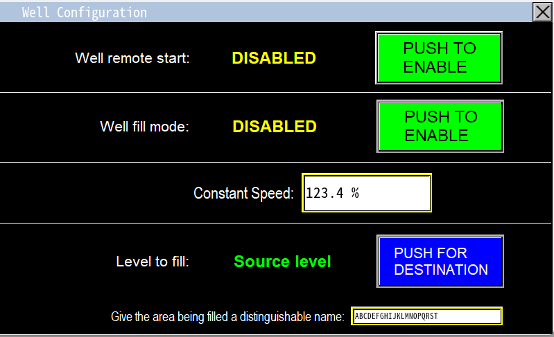
The configuration screen displays additional automation options for the well pump (Image 2.6).
Remote Start
- If enabled, a remote start allows an external controller to command the well pump to start and stop.
Well Fill Mode (Tank/Pond Fill)
- Distinct from line fill mode, Well Fill Mode is used when the Well’s purpose is to fill a tank or pond.
- When enabled, a prompt appears to assign a recognizable name to the area being filled (for example, “POND”) (Image 2.7).
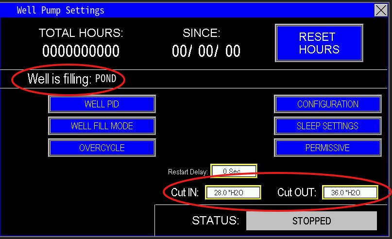
- The Well Settings screen will then show the assigned name and the cut-in/cut-out start/stop values (Image 2.8).
- Well Fill Mode requires a Well Source Level Transmitter. With a level transmitter, the pump will start at the entered cut-in level (e.g., 28 "H2O) and stop at the entered cut-out level (e.g., 30 "H2O).
Constant Speed
- The Constant Speed field lets you select a fixed operating speed for the well pump. When used, the pump will not follow PLC PID control.
- If a constant speed mode is required but the field is not present, contact PPS to enable this configuration.
Level to Fill
- Selects which level is used for fill control:
- Source Level: when the well supplies the tank/pond that serves as the pump station’s source.
- Destination Level: when the well is filling a tank for another system or area not tied to the control panel.
|

|
|
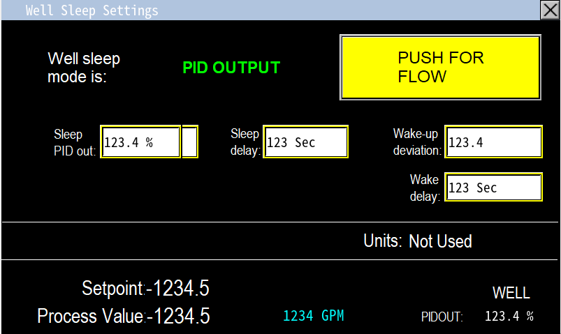
¶ Sleep Settings
Sleep Settings (image 2.9)
- Sleep behavior for the well pump matches other pumps: sleep by PID output or by flow (Image 3.0).
Displayed Information
- Setpoint: shows the well pump setpoint in the selected unit.
- Process Value: current feedback from the process variable (e.g., level or pressure transmitter).
- Example: the setpoint is 60 and configured as 60 gpm — this is factory-set and should be modified only by authorized personnel.
- PID Output: lower-right displays the PID output speed being sent from the PLC to the Well VFD.
|
|
¶ Well Pump Sensors
¶ Other Pumps
Needing to view other pumps, click from the list below: