¶ Injector pump
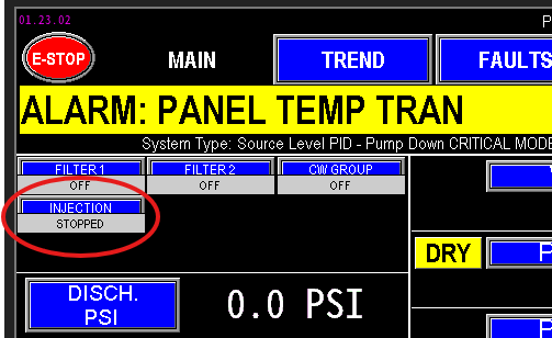
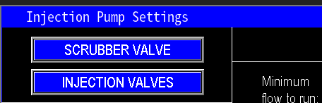
Injection Pumps are integrated into stations designed to add chemicals or other substances to the water during pumping. These pumps work in coordination with injector valves to precisely control the amount of substance introduced into the water line. To access the Injector Pump Settings page, navigate through the main screen (Image 1.1).
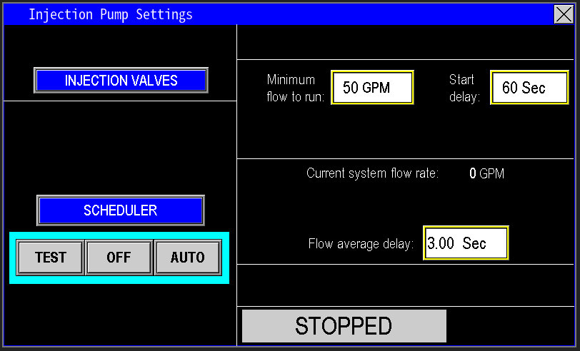
When enter into the settings page for the injector pump (image 1.2) the configuration of the injector pump can be adjusted here.
¶ Injection Valves
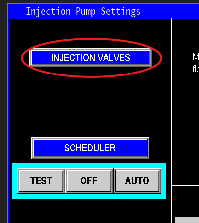
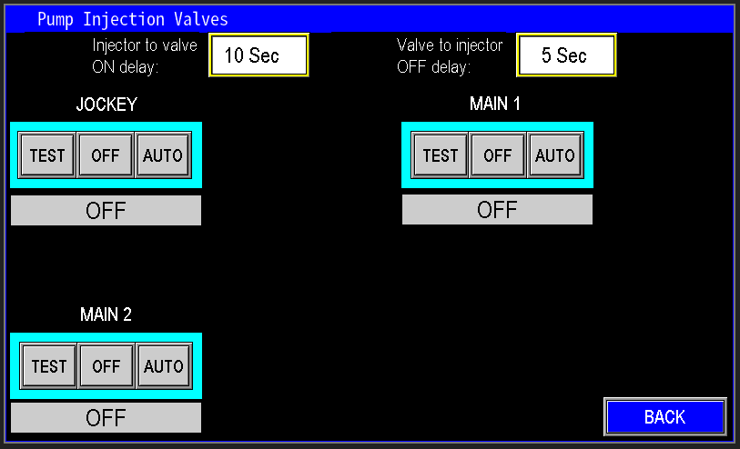
The injection valves button (image 1.3) navigates to the injection valves settings (image 1.4). For information on how to control the Injection valves, navigate to the station valves section.
|
|
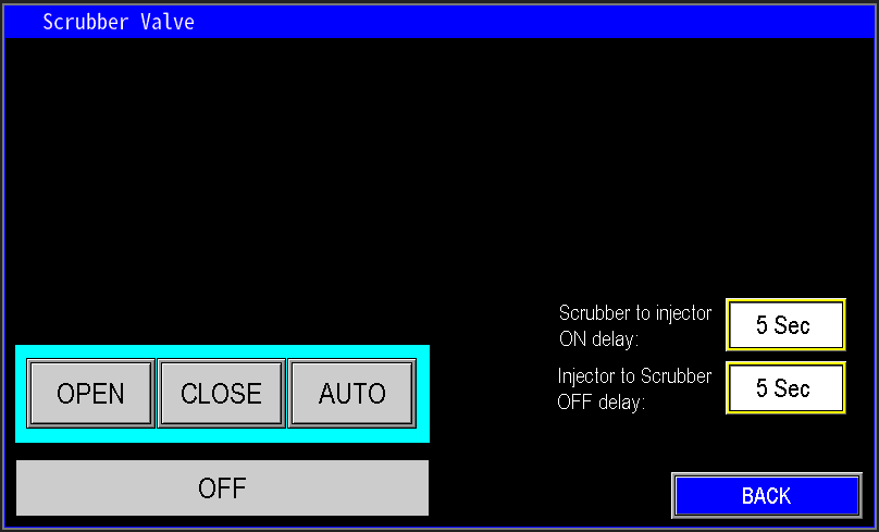
¶ Scrubber Valve
The scrubber valve button (image 1.31) navigates to the scrubber valve settings (image 1.41). Navigate to the station valves section for more information on the automation pertaining to the Scrubber Valve.
|
|
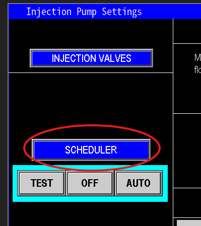
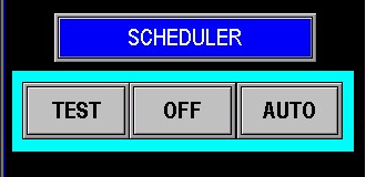
¶ Scheduler
The Scheduler (Image 1.5) functions similarly to a sprinkler system scheduler but is designed for simpler setup and operation. It allows you to automate the run times for both the injection system and the pump station. Use this feature to program precise schedules for when the station and injection pumps should operate.
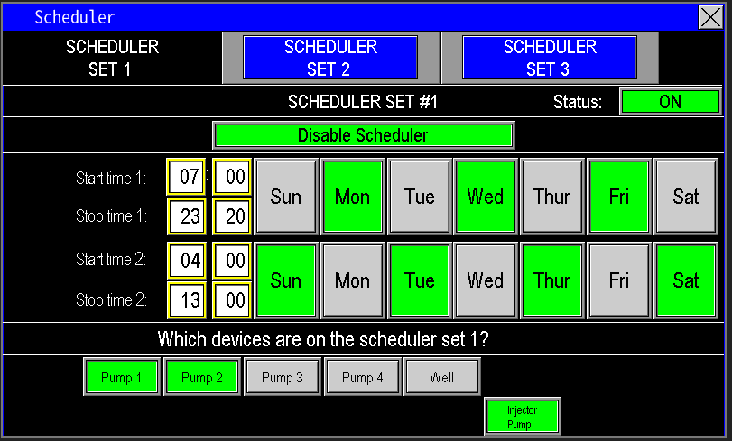
When configuring the Scheduler (Image 1.6), ensure that the injection pump is set to run alongside other pumps by verifying it is highlighted green, indicating it is selected for the scheduled time. This ensures synchronized operation with the station’s pumps.. For more information on how to set up the scheduler see the scheduler under the Main Menu Section.
¶ Virtual Operator
The Virtual Operator (Image 1.7) controls the injection pump and operates similarly to other pump operators in the system. It has three modes:
- TEST: Enables manual control of the injection pump, keeping it running until the operator manually turns it off or switches it to Auto.
- OFF: Completely stops the injection pump.
- AUTO: Allows the pump to operate automatically based on the PLC’s automation settings.
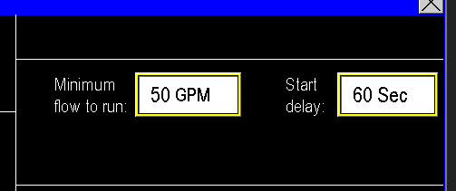
¶ Minimum to run and delay
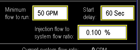
The Injector Pump is programmed to activate when the main pumps are running, with further automation provided by the Minimum Flow to Run and Start Delay settings (Image 1.8). These settings ensure the injection system only starts when a specified water flow rate is achieved. The PLC monitors the flow and waits until it reaches the set threshold. Once the flow meets or exceeds this value, a timer delay begins. If the flow remains above the threshold for the entire delay duration, the injection system activates. For example, if the flow reaches 50 GPM and maintains that level for 60 seconds, the injection system will start.
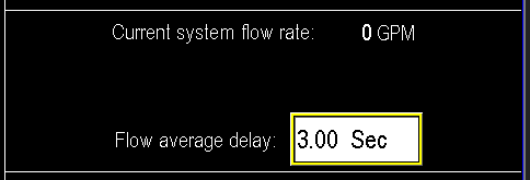
¶ Flow average delay
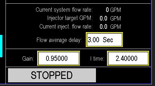
The Flow Average Delay automates the tracking of system flow by sampling it every 3 seconds, or whatever time is configured (Image 1.9). The injector system operates based on this 3-second flow average. If the flow drops below the required threshold during this period, the injection system will continue running until the 3-second delay timer elapses. Once the timer expires, the PLC detects the flow dropout and stops the injection system.
¶ Injection Flow Meter configuration
When an Injection Flow Meter is configured in the system, the automation becomes slightly more complex, and the interface updates to reflect this, as shown in Image 1.91. The injection flow meter provides additional data for precise control of the injection system, allowing the PLC to monitor and adjust based on the flow of the injected substance
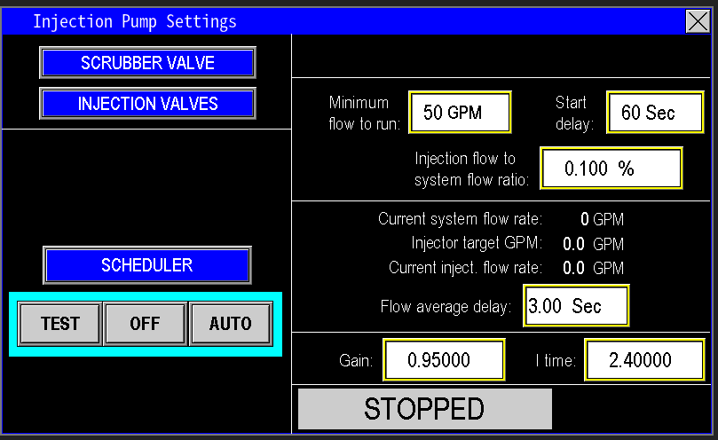
With an Injection Flow Meter configured, the Minimum Flow to Run section includes an additional data register for the Injection Flow to System Flow Ratio (Image 1.92). In this setup, the PLC calibrates the injection flow as a percentage of the system flow. For example, if the system flow is 100 GPM and the ratio is set to 0.100%, the injection system will inject approximately 0.1 GPM of chemical, equivalent to about 1/10 of a gallon of injection solution per 100 gallons of water. Proper knowledge of the chemical and the injection rate being used is essential to providing safe concentrations of water to the destination.
With the Injection Flow Meter configured, the system enables the injection pump to dynamically adjust its speed based on the required injection percentage relative to the station’s water flow. As shown in Image 1.93, thePID Controls populate to calibrate the injection pump’s variable frequency drive (VFD) speed, ensuring smooth responses to both the station’s water flow and the injection system’s flow. This PID operates based on Flow PID.
In the example provided (Image 1.93), the PLC calculates the Injector Target GPM using the current system flow rate and the Injection Flow to System Flow Ratio percentage. The screen also displays the Current Injection Flow Rate, showing the actual flow of the injection solution as measured by the injection flow meter, compared to the target flow set by the PLC. Using this data, the injection pump automatically speeds up or slows down to match the required injection flow. See the PID controls section for optimizing the injection pump’s performance for precise dosing.
¶ Status
The indicator lamp at the bottom of the screen image 2.0) will show the state of the injector pump, whether it is off, running, faulted etc.

¶ Other Pumps
Needing to view other pumps, click from the list below: