¶ Main Pump Settings
Common pump settings that apply to the Jockey, Intermediate, Main, and Well pumps are found here:
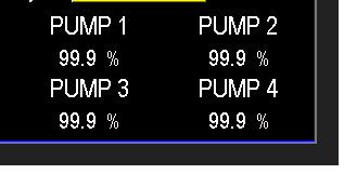
The Main Pumps are the core workhorses of the pump station, designed to meet the engineered specifications for pressure and flow. To access the Main Pump Settings, select any of the PUMP 1, 2, 3, or 4 buttons on the main screen (Image 1.1) or navigate through the MENU screens.
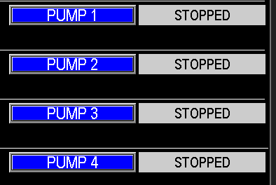
The Main Pump Settings screen (Image 1.1) is consistent in appearance for all main pumps, ensuring a uniform interface. However, each pump has its own dedicated page due to unique data such as the Hours, Totalizers, and Pump Status. While all main pumps operate similarly based on these settings, adjusting settings for one pump will apply to all Main Pumps on the station. Be mindful that changes made to one pump’s settings will impact the operation of all main pumps.

¶ Main Pump Run Totals
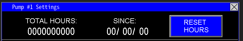
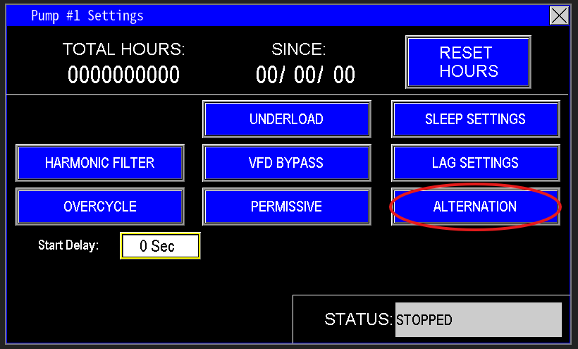
This section of the screen (Image 1.2) displays information specific to the selected main pump, such as Pump 1 in this example. It shows the Total Hours the pump or motor has run and the Since date, indicating when the hours were last reset. The Reset Hours button applies only to the specific pump selected, resetting its Total Hours to zero and updating the Since date to the current date. This feature is an effective way to track the operational lifespan of each pump or motor, particularly useful when a pump or motor is replaced due to a breakdown.
¶ Start Delay and Status
The Start Delay for the main pumps (Image 1.3) is a customizable timer that adds an extra delay before the pump starts. The Omnia program includes built-in timers to ensure the main pump’s starting sequence is executed safely, preventing interference with other station components or automation. If additional time is needed to enhance the pump station’s performance for specific applications, this adjustable timer allows you to tailor the delay to meet those requirements.
The Status display indicates the current state of the main pump, such as STOPPED, STARTING, RUNNING, FAULTED, or other relevant states.

¶ VFD Bypass Settings
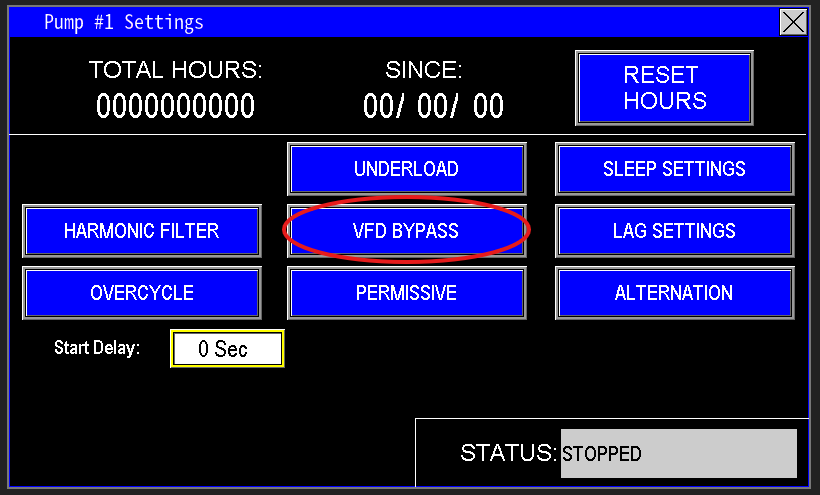
The VFD Bypass Mode (Image 3.0) disables the variable frequency drive (VFD), preventing it from slowing down the pump. When enabled, this mode impacts the automation of lag pumps, as the system relies on the lead pump’s hertz output to determine when lag pumps activate. Operating in bypass mode should not be done unattended, as it is intended strictly for emergency use. This mode is password-protected and should only be accessed by authorized personnel.
¶ Lag Settings
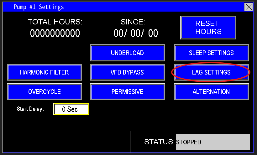
Lag Pumps (Image 3.1) are the main pumps that activate after the lead main pump is running but unable to meet the station’s water demand. These settings must be carefully configured based on the main pumps’ performance and the station’s required flow. Improper configuration can cause high pressure spikes when a lag pump starts, potentially affecting system stability. Understanding and accurately setting these parameters is critical for smooth operation.
¶ Lag Interlock
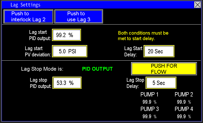
Lag Settings (Image 3.2) are critical for ensuring the pump station operates effectively. Proper configuration of these settings is essential to avoid issues like pressure spikes or inefficient performance. Pay close attention to the guidance in the Omnia Manual and monitor how the station responds when the lag pumps activate to fine-tune these settings for optimal operation.
Lag Interlocks (Image 3.3) enable the locking out of a lag pump to prevent it from activating, which is useful when the system cannot handle the full load of all main and lag pumps running simultaneously. This feature provides the flexibility to manage the station’s capacity effectively.
Only one lag pump can be interlocked at a time. To ensure the station can utilize all available pumps, press the Push to Use Lag X button for the desired pump. To prevent a specific lag pump from turning on, press the Push to Interlock Lag X button.

Many pump stations are equipped with a Backup Generator (Images 3.4 & 3.5) to maintain operation during power outages. When utility power fails, the generator starts and powers the station. However, the generator’s output capacity can limit the station’s full capabilities. If the generator is undersized and cannot support the full load of all pumps, the system can be configured to manage which pumps operate.
The Push to Keep Lag on ATS Signal button (Image 3.4) indicates that the automation assumes the generator lacks the capacity to power all pumps simultaneously. In this case, the system prevents all lag pumps from activating while the generator is running, ensuring stable operation within the generator’s limits.
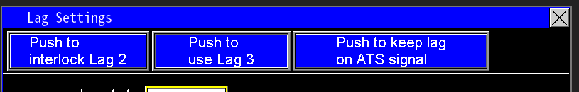
When the button displays “Push to Shed 1 Lag on ATS Signal” (Image 3.5), the automation assumes the backup generator has sufficient capacity to power the full capabilities of the pump station. In this configuration, the system allows all pumps, including lag pumps, to operate normally unless one lag pump is intentionally shed (disabled) to manage load or optimize performance while on generator power.

¶ Lag Start
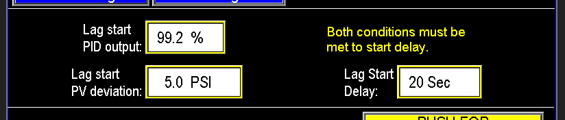
The Lag Start process for lag pumps depends on three key parameters: PID Output of the Lead Pump, Lag Start PV Deviation, and Lag Start Delay (Image 3.6). Both conditions—Lag Start PID Output and Lag Start PV Deviation—must be met to initiate the start delay.
In the example provided:
- The Lag Start PID Output requires the lead pump’s PID output to reach 99.2%, indicating the lead pump is operating at full speed.
- The Lag Start PV Deviation (Process Variable Deviation) is set to 5 PSI. This means the station’s current pressure must be at least 5 PSI below the setpoint. For instance, if the station’s setpoint is 65 PSI, the current pressure must be 60 PSI or lower.
If both conditions are satisfied for the entire duration of the 20-second Lag Start Delay, the first lag pump will activate. This process repeats sequentially for each lag pump in the station.
¶ Lag Stop
The Lag Pump Stop process is governed by two modes: PID Output and Flow (Images 3.7 & 3.8).
In the Lag Pump Stop PID Output mode (Image 3.7), the system monitors the PID output of the main (lead) pump and the Stop Delay timer. In the example provided, if the main pump’s PID output drops below 53.3%, the stop delay timer starts. If the PID output remains below 53.3% for the entire 5-second stop delay, the lag pump will turn off. To optimize this setting, carefully observe the main pump’s PID output before and after the lag pump starts and stops to determine the appropriate PID output threshold for deactivating the lag pumps.

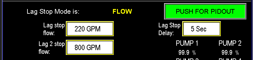
The Lag Pump Stop by Flow mode (Image 3.7) requires two conditions to be met for a lag pump to stop. In this mode, the PLC monitors the station’s current flow. If multiple lag pumps are present, each will have its own Lag Stop Flow setpoint to determine when it should deactivate.
In the example provided:
- If the station’s flow falls below 800 GPM, the Stop Delay timer starts. If the flow remains below 800 GPM for the entire 5-second duration, the Lag 2 Pump will stop.
- As flow continues to decrease and reaches the 220 GPM setpoint for Lag 1 Stop, the same process applies, stopping the Lag 1 Pump after the 5-second delay.
Proper calibration of these flow setpoints is critical to ensure lag pumps stop only when they are no longer needed. Setting the Lag Start setpoint too low or the Lag Stop setpoint too high can cause excessive cycling of the lag pumps, leading to wear and inefficiency.
¶ Lag Stop PID Output Reference
The Lag Settings Screen (Image 3.8) provides the PID Output Reference for each pump, allowing you to fine-tune settings without navigating away to monitor the station’s performance. This feature streamlines the calibration process by displaying real-time PID output data for each pump directly on the lag settings interface, ensuring accurate adjustments to optimize lag pump operation.
¶ Alternation
The Alternation function (Image 3.9) enables the main pumps to rotate the role of the Lead Pump, which operates the longest during a watering cycle. Without alternation, the same pump would consistently serve as the Lead, accumulating more run time and experiencing greater wear and tear, leading to earlier replacement. By alternating the lead pump, this function distributes operational load evenly across the main pumps, extending their lifespan.
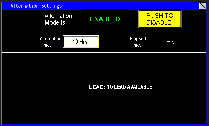
The Alternation function (Image 4.0) is automated based on a customizable timer. When Enabled, the station alternates the lead pump role according to the time interval set in the value box. In the example provided, the pumps alternate as the lead every 10 hours. The Elapsed Time display shows how long the current pump has been serving as the lead while in its running state, not idle.
If Alternation is Disabled, the station will only change the lead pump in specific situations, such as when a fault occurs or if the operator for the lead pump is turned off. In these cases, the automation will automatically select another pump as the lead, and reset the timer.
The Push to Alternate button (Image 4.1) serves as an input to the PLC, allowing you to manually force the station to alternate the lead pump. While the station is running, the screen displays which pump is currently designated as the lead. If all pump operators are set to the Off position, no lead pump will be assigned.

The ability to configure whether the station alternates lead pumps while running or only when not running is available in the Admin Settings, which are password-protected. For guidance on selecting the appropriate configuration or for any related questions, contact PPS services.
All other settings for the Main pump are detailed in the Pump Settings section, which correspond to the settings of the other pumps.
¶ Other Pumps
Needing to view other pumps, click from the list below: