¶ Sleep Settings
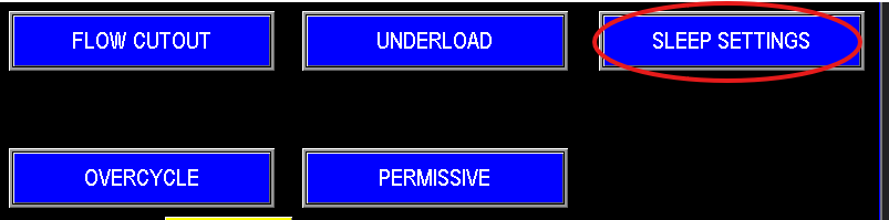
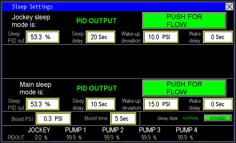
The Sleep Settings allow the pump station to automatically slow down and shut off when water demand ceases, as shown in Image 2.6. These settings, accessible via the shared sleep settings screen for the Jockey Pump, Main Pumps, and Intermediate Pumps (Image 2.7), optimize energy, efficiency and system longevity. Pumps can be put to sleep in two primary ways: Sleep by Flow or Sleep by PID Output. Additionally, if the station is configured as a pump-down system, a Sleep by Level setting will also be available, described below under “Sleep By Level” section.
|
|
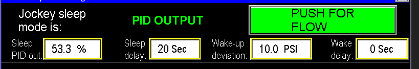
With the Sleep by PID setting (Image 2.8), the PLC monitors its own PID output sent to the variable frequency drive (VFD), as shown in Image 3.0. For example, if the PID output falls below 53.3%, the PLC initiates a 20-second delay timer. Once this timer completes, the Jockey pump enters sleep mode. The Wake-Up Deviation determines when the pump reactivates, based on the difference from the pressure setpoint. When water demand increases, causing the system pressure to drop below the setpoint by 10 psi, the pump is triggered to wake up and resume building pressure. Additionally, a Wake-Up Delay timer can be set to delay the pump’s restart after the wake-up deviation setpoint is met. Once the deviation is detected, the wake-up delay timer starts, and upon completion, the pump restarts.
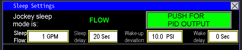
With the Sleep by Flow setting (Image 2.9), the PLC monitors the flow meter reading to manage the pump’s sleep mode, functioning similarly to the Sleep by PID feature described earlier. The key difference is that instead of triggering sleep mode based on a drop in PID output, the PLC initiates sleep mode when the flow rate falls below the designated setpoint. For example, if the flow drops below 1 GPM, the Jockey pump will enter sleep mode after the configured delay timer (as set in the sleep settings) completes.
¶ Sleep by Level
The Sleep by Level feature is added to Omnia when the station is configured as a pump-down system, set during the initial factory setup in the Admin settings. In this configuration, the sleep settings screen will differ slightly, displaying a Push for Level option instead of Push for Flow, as shown in Image 3.0. This allows the PLC to monitor the liquid level to trigger sleep mode, rather than flow or PID output.
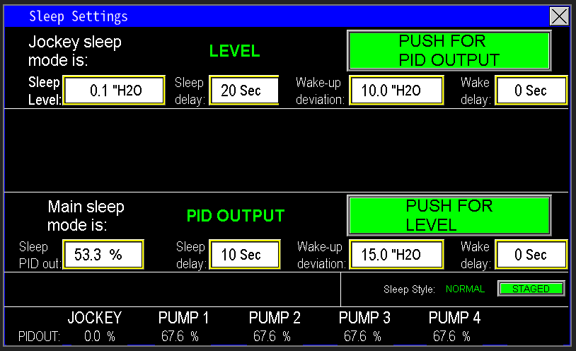
At the bottom of the screen (Image 3.1), the PID readout displays real-time data for all pumps. When calibrating the Sleep by PID setting, comparing the pump speed with the PLC’s output to the drive can help determine the optimal value for the Sleep by PID Output setting, as shown in Image 2.8. This ensures precise configuration for entering sleep mode efficiently.

¶ Pumps
For more specific settings pertaining to a particular pump click one of the pump links below: