¶ Well Pressure Settings
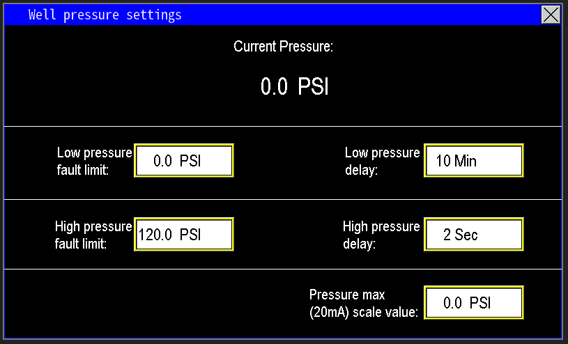
The Well Pressure settings govern the pressure used specifically for controlling the well pump. These settings are independent of the station’s other pressure transmitters and affect only well‑pump operation (image 1.1).
¶ Current Pressure
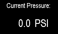
The current pressure reading (image 1.2) shown on this screen relates solely to the well pump connected to the pump station panel. It is not connected to or affected by the station’s discharge transmitters. In most applications, this well pump fills a tank or sump from which the station then pumps water out. The well-side pressure transmitter only controls the speed of the well pump and does not influence the operation of the station’s other pumps.
¶ Low pressure fault limit and delay
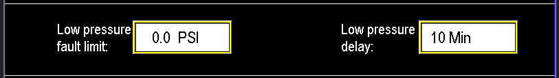
This feature uses two parameters: the Low Pressure Fault Limit and the Low Pressure Delay (image 1.3).
- If the pressure sensor reading falls below the fault limit, the delay timer starts.
- Once the timer elapses, the well pump circuit faults due to low pressure.
The delay allows the pressure system to recover before shutting down the pump. If the pressure stabilizes above the fault limit during the delay, the timer resets, and the well pump continues operation normally.
¶ High pressure fault limit and delay
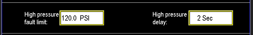
The high-pressure protection functions similarly to the low-pressure setup but features a much shorter fault delay—typically within a few seconds—to quickly protect system components (image 1.4). Set the high-pressure limit based on the maximum PSI rating of the weakest component to prevent damage. When the pressure exceeds this limit, the system faults and shuts down immediately. This protection applies only to the well pump circuit; other parts of the system are unaffected.
¶ Transmitter scaling
To ensure accurate readings, match the transmitter’s maximum range to the Pressure Max (20 mA) scale value (image 1.5). At the transmitter, record the maximum pressure span and input that number into the Pressure Max (20 mA) field. This calibration step ensures the PLC or SCADA system displays correct well pressure readings.