¶ Intake Pressure Settings
Intake pressure settings monitor the pressure feeding the station inlet. The intake source may be a gravity-fed tank or pond, or the discharge from another station (image 1.1).
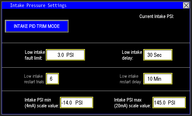
¶ Low intake fault limit and delay
This feature protects pumps by monitoring intake pressure to ensure adequate water supply (image 1.2). It uses two parameters:
- Low Intake Fault Limit: the minimum acceptable intake pressure.
- Low Intake Delay: the time the reading must remain below the limit before a fault is triggered.
If intake pressure falls below the fault limit, the delay timer starts. If the condition persists until the timer elapses, the station faults on low intake pressure to protect the pumps. If intake pressure recovers before the delay expires, the timer resets and normal operation continues.

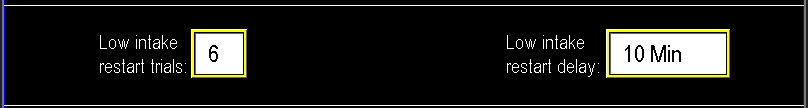
¶ Low intake restart trials and restart delay
This feature limits how many times the station may fault and automatically restart for low intake pressure (image 1.3).
- Low Intake Restart Trials: maximum number of automatic fault/restart attempts allowed.
- Low Intake Restart Delay: minimum time the station remains in a faulted state before an automatic restart is attempted.
Restart conditions:
- The intake pressure must recover above the low intake alarm limit for the restart delay to begin.
- If pressure remains below the alarm limit, the station stays faulted until manually reset.
If the station exhausts the allowed restart trials, any subsequent low-intake fault will remain latched and require personnel intervention to investigate and reset.
¶ Intake PSI min (4mA) scale value and max (20mA) scale value
The PSI Min and Max scale values define the pressure range corresponding to the intake transmitter output (image 1.4). Enter the pressure that corresponds to the transmitter’s 4 mA output as the Min (4 mA) scale value, and the pressure that corresponds to the 20 mA output as the Max (20 mA) scale value. These adjustable ranges allow replacement with a transmitter that has a different span without requiring PLC reprogramming.
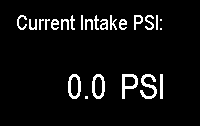
¶ Current Intake PSI
This value displays the live pressure reported by the intake transmitter to the PLC (image 1.5).
¶ Intake PID trim mode
This selectable mode reduces pump speeds as intake pressure falls to extend run time when the station is nearing low-intake conditions (image 1.6). Enable PID Trim when a station is repeatedly faulting for low intake pressure so the pumps can continue supplying flow longer as intake pressure declines.
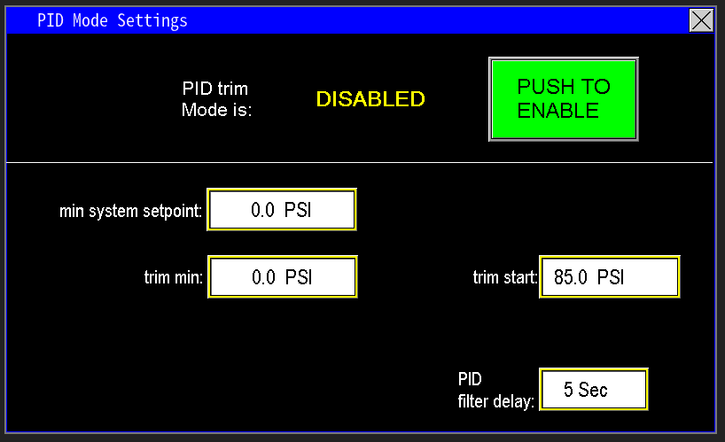
¶ Trim min and trim start
Trim Start and Trim Min define the level-based scaling the PLC uses to compute a reduced discharge setpoint (image 1.7):
- Trim Start: the intake pressure at which the PLC begins PID trim action because intake is declining to a concerning level.
- Trim Min: the lowest intake pressure at which the pumps may operate without running dry.
Between Trim Start and Trim Min the PLC progressively lowers the discharge setpoint to reduce pump speed and extend available run time.

When PID Trim is active, the PLC progressively lowers the discharge pressure setpoint to compensate for falling intake pressure. The setpoint continues to reduce as intake pressure declines until it reaches the configured Minimum System Setpoint (image 1.8).
Minimum System Setpoint
- The Minimum System Setpoint is the lowest discharge pressure at which the system can still operate effectively.
- Example: if normal discharge is 75 psi but acceptable operation continues at 55 psi, set the Min System Setpoint to 55 psi. PID Trim will not reduce the discharge setpoint below this value; if intake conditions worsen past this point, the station will fault on low intake.

¶ PID Filter Delay
The PID Filter Delay defines the interval between successive PID adjustments (image 1.9). A longer delay slows the station’s response to changing intake pressure, while a shorter delay yields more frequent setpoint updates and faster reaction to level changes.