¶ Pre-filter Pressure Settings
Stations with a water filter require additional monitoring to maintain reliable operation. A Pre‑Filter transmitter measures the pressure upstream of the filter to determine the pressure differential across the filter (upstream minus downstream). This differential indicates filter loading and serves the same purpose as a PSID switch but provides greater accuracy and configurability.
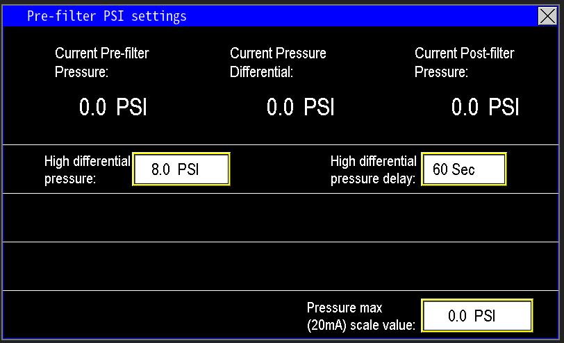
The Pre‑Filter settings screen (Image 1.1) enables monitoring of filter condition and configuration of automation actions (e.g., alerts, backwash, or maintenance reminders) based on the measured pressure differential.
A PSID switch mechanically detects pressure differential and sends a PLC signal when the filter is sufficiently dirty to require flushing. Mechanical switches, however, can fail—causing either no flushing or continuous flushing—necessitating switch replacement or an upgrade.
A pre‑filter transmitter provides a more reliable alternative. It continuously measures the upstream pressure and lets the PLC calculate the differential, enabling configurable, accurate filter monitoring. This approach reduces failure modes and gives operators flexibility to decide when to clean the filter rather than relying on a single mechanical switch.
¶ Current Pre-filter Pressure
This value displays the live pressure measured by the pre‑filter transmitter (image 1.2). It represents the pressure downstream of the pumps and upstream (inlet side) of the filter.
¶ Current Pressure Differential
The Current Pressure Differential (image 1.3) shows the real‑time pressure loss across the filter. It is calculated by subtracting the discharge pressure (downstream of the filter) from the Pre‑Filter pressure (upstream).
Example: Pre‑Filter = 50 psi, Discharge = 45 psi → Differential = 5 psi.
¶ Current Post-filter Pressure
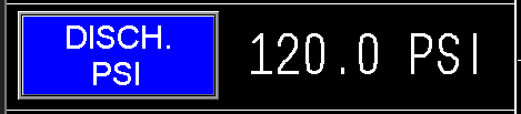
This value displays the live pressure measured downstream of the filter (post‑filter)(image 1.4). It represents the pressure delivered to the application (e.g., irrigation system or potable supply). This reading is also shown on the main screen as Discharge Pressure (Image 1.5).
|
|
¶ High Differential Pressure and delay
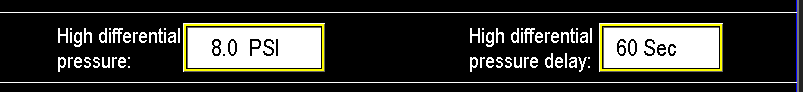
The High Differential Pressure setting (image 1.6) determines the pressure differential at which the automation initiates filter cleaning. This value is user‑configurable; the factory default is 8 psi. Select an appropriate differential based on system flow rate, incoming debris load, and filter screen size—higher flow or finer screens typically require a lower differential threshold for timely cleaning, while coarser screens or lower debris loads may allow a higher threshold.
The High Differential Pressure Delay sets how long the differential must remain above the high‑differential threshold before the filter‑cleaning sequence begins. Transmitter noise or transient flow changes can cause brief spikes in differential pressure; the delay prevents unnecessary flush cycles by requiring the condition to persist for the configured duration.
Example: if the high differential is 8 psi and the delay is 60 seconds, the differential must remain >8 psi for 60 seconds before the automation opens the flush valve to clean the filter.
¶ Transmitter Scaling
To ensure accurate readings, set the Pressure Max (20 mA) scale value to match the transmitter’s maximum range (image 1.7). At the transmitter, note its maximum pressure range and enter that value into the Pressure Max (20 mA) field so the PLC/SCADA displays correct values.
¶ Processes With Pre-filter Transmitter
Other processes included with a Pre-filter Transmitter are: