¶ Filtration and Filter Settings
Some of these settings coincide with the Pre-Filter Transmitter.
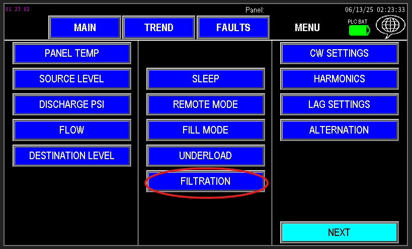
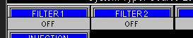
The Filtration tab provides a comprehensive overview of all filters installed on the station (image 1.1). This is also accessible via the main screen (image 1.2). It displays the current status and activity of each valve, helping operators quickly assess what each valve is doing and its operational state. Additionally, this tab allows for quick access to control individual valves directly or to enter each filter’s settings. In the settings, you can review and adjust parameters specific to each filter, ensuring optimal performance and maintenance management.
|
|
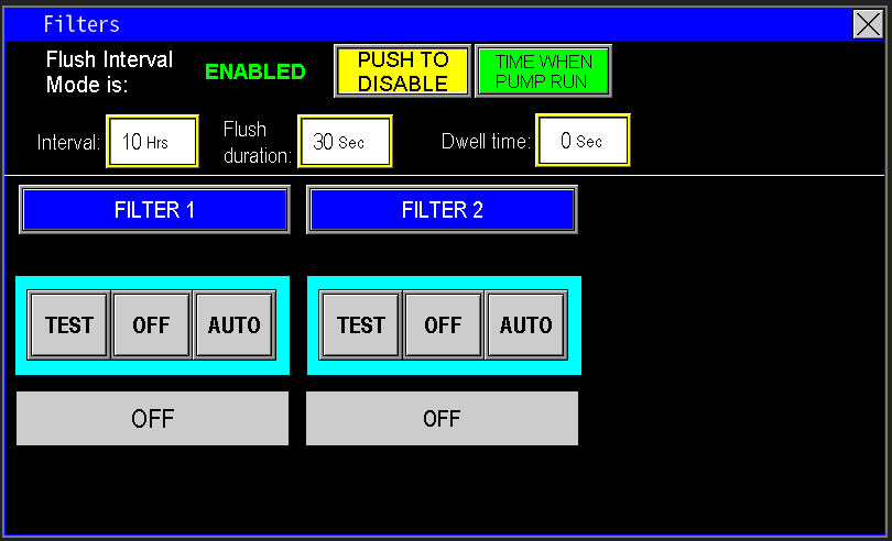
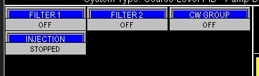
Once accessed, the filtration screen will display a list of all filters connected to this pump station (image 1.3). It provides detailed information on each filter's current status and allows for individual control or configuration of settings specific to each filter component.
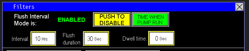
¶ Flush Interval Mode
When enabled, the Flush Interval Mode activates a schedule for automatic filter flushing based on time intervals. This is especially useful when water quality is inconsistent, allowing the station to maintain clean filters by flushing at a set rate measured in hours (image 1.4).
"Time When Pump Runs" Button:
This option ensures the interval countdown only advances when the pumps are actively running. For example, if the interval is set to 10 hours, the timer will count only the hours during which the pump is operating (as in the example below, (Image 1.3).
- If enabled, the flush will only occur after the pump has been running for the specified number of hours.
- If disabled, the flush will trigger every set number of real hours regardless of pump activity.
Automatic Reset:
If a filter trigger occurs before the timer completes, the timer will reset and start counting down from the full interval again.
Dwell Time:
This setting applies to systems with multiple filters, controlling the time gap between the first filter’s flush stopping and the second filter’s flush starting, ensuring proper sequencing and back-to-back cleaning cycles.
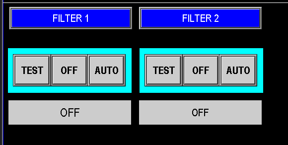
¶ Virtual HOA
The Virtual HOA allows manual control over the filter operation (Image 1.5):
Test: Manually cycles the filter valve on and off, useful for testing or manual flushing procedures. If the filter includes a flushing motor, this mode will also activate that motor to perform the proper cleaning cycle.
Off: Disables the filter operation, turning the valve and flushing motor off.
Auto: Enables PLC automation to control the filter's flushing cycle based on configured schedules and sensor inputs.
To adjust specific parameters or setpoints for an individual filter, select that filter from the list and access its detailed settings. These can also be accessed quickly from the main screen by clicking the filter button (Image 1.6). These can also be configured into filter groups as well. This is configured in the Admin Section which is password protected.
All filter screens share a similar layout and interface, providing a consistent user experience. Depending on the specific pump station configuration, the automation control logic may vary slightly—for example, whether the filter includes a flushing motor or not. However, most control features and settings are present across all configurations, ensuring comprehensive management and easy operation regardless of the filter type installed.
|
|
¶ Filter Usage
At the top of the filter screen (image 1.7), the display shows the total hours of filter operation for this station. In configurations without a flushing motor, these hours represent how long the filter valve has been open or active. If the filter includes a motor to assist with flushing, the hours also indicate the total runtime of that motor during flush cycles. This information helps track filter activity and maintenance needs.
Cycle Count and Reset Information
Cycles: Indicates how many times the filter flush sequence has been initiated and the filter has been activated. This helps track usage and frequency of cleaning cycles.
Since: Shows the date and time when the hours and cycle count were last reset, such as after maintenance or component replacement.
Reset Hours Button: Pressing this button resets both the hours and cycle count to zero and updates the “since” date to the current date and time on the HMI, providing a fresh starting point for monitoring filter activity.

¶ Flush Interval Mode
When enabled, the Flush Interval Mode activates a schedule for automatic filter flushing based on a set time interval, measured in hours. This is particularly useful when water quality is variable, ensuring the filter remains clean by flushing at regular, user-defined intervals (image 1.8).
"Time When Pump Runs" Button:
This option allows the interval timer to only accumulate during periods when the pump is actively running.
- For example, if the interval is set to 10 hours (as shown in Image 1.9), the timer will count only the hours that the pump is operating before triggering a flush.
- If this option is disabled, the filter flush will be triggered every 10 real hours regardless of pump activity.
Automatic Reset:
If a flush command occurs before the timer completes, the timer resets and begins counting down again from the full interval after the flush, ensuring consistent schedule adherence.
This setup helps maintain clean filters efficiently, especially in systems with fluctuating water quality.
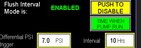
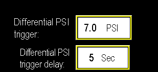
¶ Differential PSI trigger and delay
Traditionally, filters with a PSID switch rely on a mechanical device to detect when pressure difference indicates a dirty filter. When the switch closes, it signals the PLC to initiate a flush. However, PSID switches can fail over time, leading to potential undetected dirt buildup.
With Omnia and the addition of a pre-filter pressure transmitter, the system can now measure the pressure difference directly through the PLC by monitoring two transmitters: upstream and downstream of the filter.
The differential PSI trigger (Image 1.9) is adjustable, allowing operators to set the pressure difference threshold. When the PLC detects that the pressure differential exceeds this setpoint, it starts a delay timer. If the pressure difference remains above the setpoint for the duration of this timer, the PLC will automatically initiate the filter flush, ensuring continuous monitoring and eliminating dependence on the mechanical switch.
¶ Virtual HOA and push to test valve
For filters equipped with a motor that operates during the flushing cycle, the control screen (Image 2.0) includes a "Push to Test" valve button. When pressed, this button allows independent testing of the valve itself without activating the motor, and the status of the test is displayed below.
In configurations where the filter does not have a motor (Image 2.1), this test button is not visible. Instead, the virtual HOA (Image 2.2) uses its own control to turn the filter flush valve on, providing a manual override or test function separate from the motorized flushing sequence.

|
|
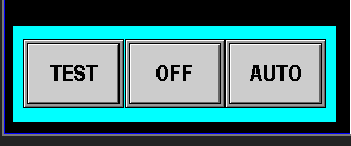
In configurations where the filter includes a motor, the test button on the Virtual TOA (Test, Off, Auto) will activate both the filter valve and the flushing motor to run the full flush sequence manually (image 2.2). Before performing this test, verify that any limit switches or safety devices on the motor are functioning correctly to prevent damage or safety issues.
- TEST: Manually turns on both the filter valve and the flushing motor simultaneously. This allows for testing the entire flushing operation manually. The system will keep both the valve and motor on until it is switched to OFF or AUTO mode.
- OFF: Turns off the entire filter system, stopping both the valve and the motor.
- AUTO: Allows the PLC automation to control the filter flushing process based on your system’s programmed logic and schedule.
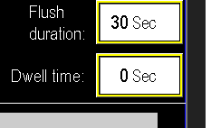
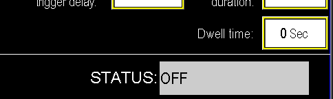
¶ Dwell time and flush duration
In systems with two filters, each filter will have its own dwell time and flush duration settings (image 2.3).
Flush Duration:
This is the length of time the filter’s flush cycle runs each time it is activated.
Dwell Time:
This is the waiting period between the end of one filter’s flush and the start of the other filter’s flush cycle, ensuring proper sequencing and avoiding simultaneous operation.
These settings help coordinate the cleaning cycles to maintain filter effectiveness while optimizing system performance.