¶ Admin
This screen is restricted to qualified PPS personnel only. If you are not a member of the PPS organization, do not proceed. Instead, contact PPS Service for assistance and further instructions. This section is intended for advanced technicians with comprehensive knowledge of panel configuration for specific systems. Unauthorized access or use by individuals without expertise in automation can result in station inoperability.
¶ Admin Setup
The Admin function grants access to a set of advanced screens, intended for use by a limited number of personnel. Access should be restricted to individuals internal to Precision Pumping Systems that are authorize to use it.
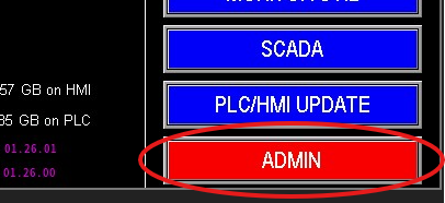
Access to the Admin screen is password-protected. Upon successful login, the Admin screen will be displayed (refer to Image 1.1).
This screen is primarily used to configure new features added to the station. During the initial panel testing and programming phase, the Admin screen is crucial for setting up the station correctly. Once the initial setup is complete, and no new features are implemented, the Admin screen will rarely be needed.
During initial panel setup, the Admin screen will automatically appear. This process requires the Omnia HMI and PLC programs to be installed. Once these programs are downloaded, the I/O must be mapped.
For PPS Technicians: I/O mapping can be performed using the I/O Configurator to create an FCDATA file (I/O map file). This file should then be inserted into the PLC via the SD slot. (Note: FCDATA files are proprietary to PPS. Contact PPS for file creation.) This process can also be completed manually, as detailed later in this document.
¶ Initial Setup
For initial panel setup in the factory, mapping the I/O is a straightforward process.
- Prerequisites: Verify that the correct Omnia programs are loaded onto both the PLC and HMI, and that an FCDATA file for the specific job is present in the designated job folder.
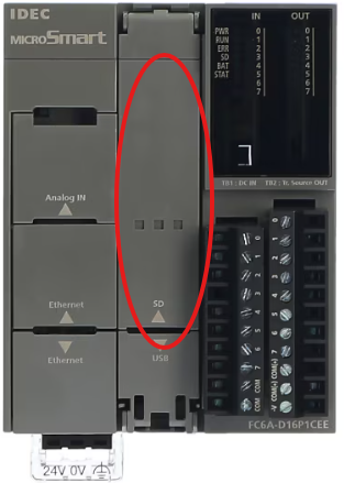
- Load FCDATA File: Copy the FCDATA file onto an SD card and insert the SD card into the SD card slot on the PLC (refer to Image 1.3).
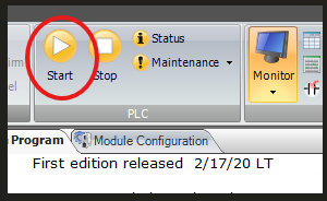
- PLC Run Mode: Ensure that the PLC is in "Run" mode (refer to Image 1.2).
- Dip Switch Verification: Locate the dip switch next to the SD card slot on the PLC. Confirm that the switch is in the "On" position (typically the "Up" position).
|
|
|
With the previous steps completed, the PLC and HMI are ready for configuration.
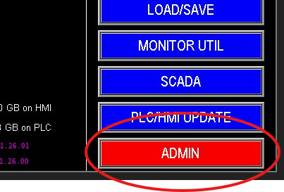
- Navigate to Admin Screen: Upon starting the panel for the first time, the Admin screen (Image 1.1) should be displayed automatically. If not, navigate through the menu screens until you locate the "Admin" button (Image 1.4) and select it.
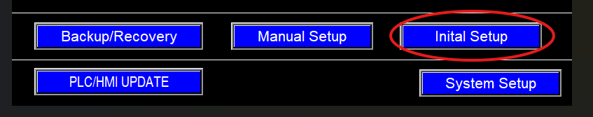
- Initial Setup: On the Admin screen, select the "Initial Setup" button (Image 1.5).
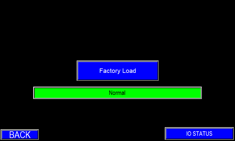
- Factory Load: On the subsequent screen, press the "Factory Load" button (Image 1.6).
If the screen matches Image 1.6 (Normal), the I/O map has been applied successfully and the system is ready to proceed. If not, refer to the Troubleshooting section.
¶ System Setup
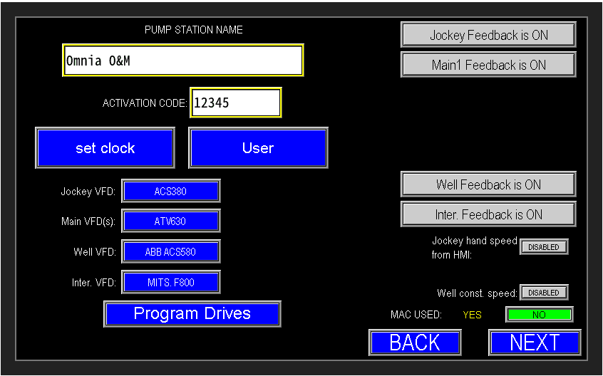
The System Setup screen (image 1.1) configures communications to motors, VFDs, switches, and other devices. It also lets you set the system date and time, manage user passwords, and name the pump station.
The pump station name and activation code are shown here. The activation code enables the automated panel after purchase; it should not be changed. During initial setup, the activation code and station name are loaded automatically when the FC Data is factory‑loaded. The station name may be edited if required.
This screen also provides virtual speed‑pot configuration for pumps that lack a physical speed pot on the door. Enable or disable the virtual speed pot using the control in the lower‑right corner of the corresponding pump section
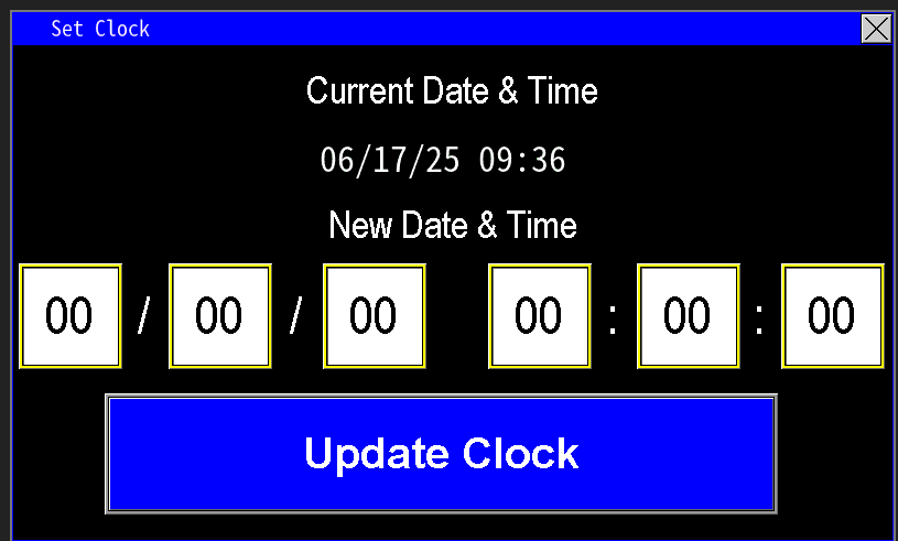
¶ Set Time and Date
Select "Set Clock" to open the clock dialog (image 1.1). Enter the date (MM/DD/YY) and time using the 24‑hour format, then press "Update Clock" to apply the changes.
All emails, records, and event timestamps use the HMI clock, so verify the date and time are correct.
Note: All fields (date and time) must be completed before updating; partial entries will not be accepted.
¶ User setup
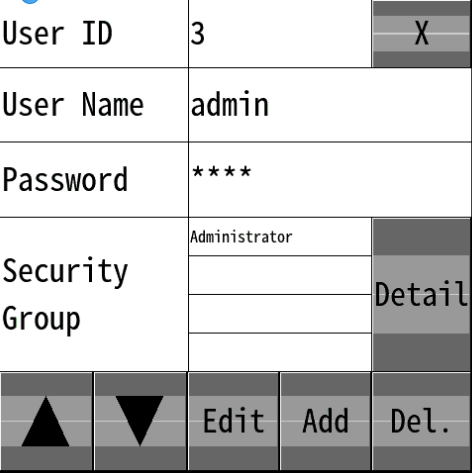
To configure HMI users, press the Users button (Image 1.1) to open the Users dialog (Image 1.2).
- Use the up/down arrows to browse existing accounts: Admin, Owner, Operator, Guest, and Special. Admin, Owner, and Special are preconfigured.
- During panel testing, set the Operator password to the job work‑order number.
- To change a password, select the user, press Edit, enter the new password in the password field, then click OK. A "Succeed" message confirms the update.
- Use Add to create a new user and Del to remove the selected user.
Configured users can remotely monitor the station provided the modem is active and the user has internet access.

|
|
¶ Programming Drives
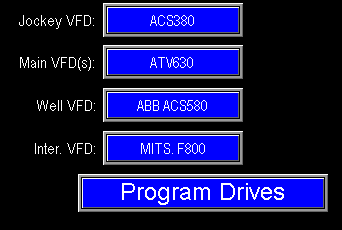
Omnia supports dynamic communication with a variety of VFD manufacturers (see Image 3.0). While some drives require vendor software for configuration, ABB drives can be programmed directly from the HMI. When configuring a drive, ensure the model shown on the screen matches the drive’s nameplate in the panel.
¶ Drive Selection
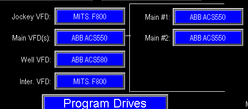
To change the drive type, press the blue button to cycle through the drives; the PLC will then use the correct communication registers for that drive model. Images 1.1 and 1.3 show the VFD's that need programmed based on the I/O configuration loaded from the initial setup section. If a drive is missing or requesting a drive not installed on the station (e.g., a Well VFD), return to the manual setup screen and update the analog output configuration to match the actual drives installed.
Note: Verify whether the panel uses MAC (Motor Alternating Contactor) operation. If MAC is enabled, one drive alternates among multiple main motors; select "MAC used: Yes" (image 1.2). If MAC is not used, each main motor has its own drive and should be configured individually—select "MAC used: No." This selection determines how the program handles lead/lag and alternation logic. If MAC is enabled, only a single main VFD option (image 1.1) appears. If MAC is disabled, options for each main pump’s VFD are displayed (image 1.2). Ensure this setting matches the physical configuration, or the pump station automation may not operate correctly.
|

|
|
¶ Program Drives (ABB)
When the drive models are configured and matched, press "Program Drives" to open the ABB drive programming screen (Image 1.4). Use "Next Drive" to cycle through and select the drive you wish to program. Repeat to scan through all drives installed in the panel.
First, configure the Ethernet communication settings for the selected drive, then proceed with the drive programming sequence.
Omnia has a static ethernet place holder for each potential drive on the station. These IP addresses go as follows:
- Jockey: 192.168.1.5
- Main 1: 192.168.1.6
- Main 2: 192.168.1.7
- Main 3: 192.168.1.8
- Main 4: 192.168.1.9
- Well: 192.168.1.10
- Intermediate: 192.168.1.11
- Recirculation: 192.168.1.20 or whatever is chosen.
¶ Jockey, Main, & Well VFD Communication Setup
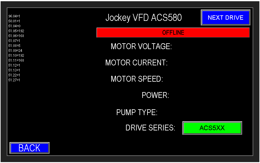
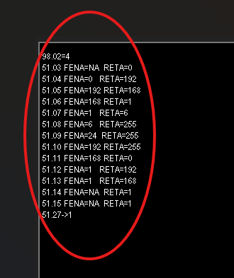
When Ethernet communication is not configured, drives will display OFFLINE (image above 1.4). The program drives screen provides a list of drive parameters that must be set to establish Ethernet communication to each specific drive (example list in image 1.5).
Before changing parameters, verify the communication module installed in the drive (FENA, RETA, FMBT, etc.) and follow the parameter list specific to that module and the selected drive model. Module parameter names and values are similar but not identical—using the wrong list can prevent successful communication.
Follow these steps for each drive:
- Configure the communication parameters in the drive using the parameter list for the installed communication module (FENA, RETA, FMBT, etc.).
- After updating the parameters on a drive, return to the Program Drives screen and refresh the page.
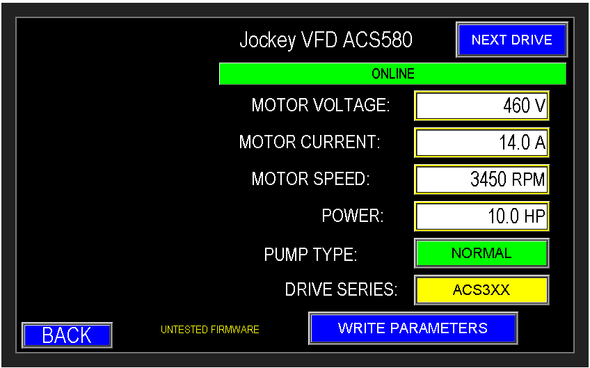
- Confirm the drive status changes from OFFLINE to ONLINE (Image 1.6).
If any drive remains OFFLINE, recheck and correct the drive’s communication parameters, then refresh the Program Drives screen and verify again.
Now enter motor data
Collect the motor nameplate data and enter the corresponding values into the parameter fields. Before writing parameters, confirm two selections:
Pump Type (Table 1): choose "Submersible" or "Normal." Submersible pumps require different speed, ramp, and protection settings than normal (surface) pumps. Select the type that matches the installed pump on the station so the PLC writes the appropriate parameters.
Drive Series (Table 2): choose the correct ABB drive series (e.g., 300 or 500). Different series use different parameter sets and I/O mappings.
After verifying motor data, pump type, and drive series, press "Write Parameters" to program the drive.
Table 1: Pump Type

|

|
Table 2: Drive Series

|

|
¶ Intermediate VFD
Programming an Intermediate VFD (Summary)
- Disconnect the Jockey VFD from the Ethernet switch (power off or unplug its network connection).
- On the intermediate drive, follow the standard drive setup steps but select the Jockey drive profile when writing parameters. The intermediate pump is configured to emulate the Jockey pump, so use the Jockey pump profile when programming the intermediate VFD.
- Enter motor nameplate data, choose pump type, and select the correct drive series; then write parameters.
- Update the intermediate VFD IP address from the default Jockey IP (192.168.1.5) to the intermediate IP (192.168.1.11):
- Locate the IP address parameter group (example: Group 51, Params 5–8) (Image 1.1).
- Change the four octet parameters to 192 .168 . 1. 11.
- Commit the IP changes (example method):
- While in the same parameter group, set the Configure parameter (Group 51, Param 27) to 1 and save, or power‑cycle the drive to apply (image 1.2).
- Reconnect/power the original Jockey VFD and verify both drives show ONLINE and the intermediate drive responds at its new IP.
Note: Parameter group/parameter numbers vary by communication module and drive series—use the correct parameter map for your module. If the drive does not accept the new IP or does not appear ONLINE after refresh, recheck the parameter entries and restart the drive.
|

|

|
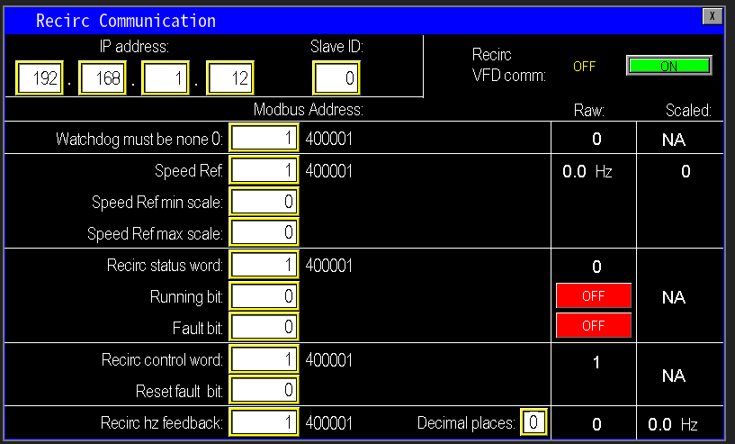
¶ Recirculation VFD Communication
The process of setting up communication to the Recirc VFD is not done here in the admin setup settings, it is done in the Recirc Pump settings page.
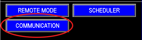
Navigate to the communication tab indicated below on the recirc pump screen and click on it (Image 1.5). This page is password protected. Once access is gained, this will populate the Recirc Communication screen (image 1.6) If equipped with a VFD, turn on the VFD communication (Image 1.7) and if not, ensure that the recirc communication is off.
|
|

|
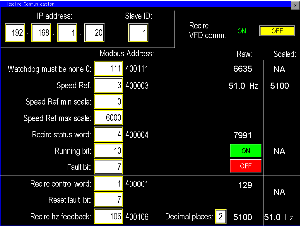
¶ VFD setup
If the panel includes a VFD, configure the PLC to communicate with that drive. The example below references an ABB ACQ580; for other drive models, follow the appropriate section for that manufacturer.
- Assign an IP address for the Recirc VFD (e.g., 192.168.1.20 or any unused address on the network).
- Program the VFD with the PPS factory parameter file. If the drive has not been programmed or is still in testing, contact PPS Engineering to obtain the correct parameter file for the recirculation pump.
- Update the VFD’s network settings so its IP address matches the address entered on the HMI screen.
- Follow the guided prompts on the HMI (Image 1.7) to enter the correct Modbus/register addresses and any other communication parameters required by the drive.
- Verify all parameters match and test communication. Once confirmed, the PLC and Recirc VFD will be correctly configured for Modbus/ethernet communication.
Note: Before running the Recirc Pump, ensure that the motor data off the pump motor match the motor data parameters in the drive (Parameter Group 99).
¶ System Setup (SCREEN 2)
Once the drives are programmed and the first screen of the system setup is done, press the next button on the bottom of the page to continue to screen 2 (image 1.1). This screen has an array of options for changes to be made to the logic of the program based on the type of instruments that are bought with the pump station. For example level floats come in normally open and normally closed, this is configurable in this screen. Based on the station package that was purchased with the control panel, the program will reflect only those options that are pertinent to the station it was built to run. Get to know the station front to back and everywhere in between to set it up and configure it to the best we can.
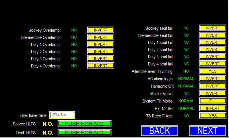
The options on this page (Image 1.1) apply only to features installed on the station; additional controls may appear dynamically if corresponding hardware is present. Descriptions and recommended settings for each configurable item follow.
Configuration Options — Descriptions
- Overtemp Switches: Set the switch orientation — Normally Open (NO) or Inverted / Normally Closed (NC).
- Filter Travel Time: For motorized filters (e.g., SAF/Amiad), enter the maximum motor run time before the filter’s limit switches must register. If the motor does not reach its limit within this time, the filter will fault. Increase the value if the filter requires a longer cycle due to size or load.
- High Level Float Switches (HLFS): Specify float switch orientation — Normally Open (NO) or Inverted / Normally Closed (NC). Also select mounting style: Hanging or Floating.
- Pump Seal-Fail: Set the seal-fail input orientation (NO or NC), same selection logic as overtemp switches.
- Alternate Even If Running: Enable to force lead rotation during continuous operation (rather than only during sleep) to distribute wear across pumps. Note: on MAC circuits or if the next lead pump is not already running, switching leads may cause a brief drop in pressure/flow while the new lead reaches speed.
- AC Alarm Logic: Configure the AC unit auxiliary contact orientation (Normal or Inverted).
- Harmonic OT: If a harmonic filter is installed, set the orientation (NO/NC) of its overtemp switch.
- Master Valve: Specify whether the master valve is Normally Open (power to close) or Normally Closed (power to open).
- System Fill Mode: Choose Normal (pressure‑based control) or Fill (Destination Fill). Destination Fill enables level‑based control and exposes Destination Level transmitter settings so the station fills to defined level setpoints rather than by pressure. Selecting Fill also enables the “sleep by level” options in the pump sleep settings — see the Sleep Settings section for details.
- Ext ½ Sel: Adjusts the external start/stop signal polarity for drives that cannot be controlled digitally (“blind” drives). Inverting this signal causes the PLC output to remain active while HOA is in AUTO, improving reliability for blind drives. This parameter may require manual configuration or adjustment via the I/O configurator.
- ITS Retro Filters: Enables support for expanded filter configurations. Standard systems typically use 1–2 filters (one flush valve per filter). ITS Retro Filters allows the station to support more than four filters and associated flush valves.
Configure each option to match the installed hardware and station design to ensure correct and reliable automation behavior.
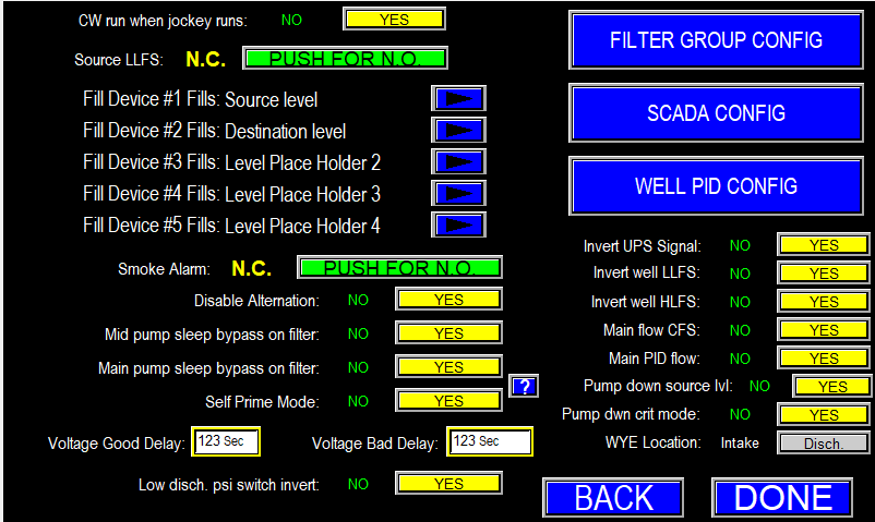
¶ System Setup Screen 3
This screen (Image 1.1) supplements Screen 2 by providing additional configuration options to match the panel to the pump station’s hardware and desired automation.
¶ Configurable options under System setup Screen 3
¶ CW Run when jockey runs
When the station uses a single intake line, the CW (clean‑water) valve typically does not operate while the jockey pump runs alone. The CW normally operates only when one or more main pumps are running; when mains stop and the station enters sleep, the jockey maintains pressure and the CW is turned off.
If the jockey pump has sufficient capacity to support CW flow while still maintaining discharge pressure and allowing the station to sleep, enable the option to run the CW during jockey operation (image 1.2).

¶ Source LLFS
Source LLFS configures the float switch used to monitor the source water level. Set the switch orientation in the logic to match the physical float installed (Normally Open or Normally Closed and hanging vs. floating) to ensure accurate level detection and proper protection of the station (image 1.3).

¶ Fill Devices
Fill Device Assignment (image 1.4)
When the station includes one or more fill devices, assign each device as either Source or Destination in the configuration. This assignment adds a clear label in the fill device settings indicating which tank, pond, or source each fill device serves (image 1.5).

|

|
¶ Smoke Alarm
Specify the smoke alarm input logic to match the installed hardware: Normally Open (N.O.) or Normally Closed (N.C.). This selection ensures the PLC interprets alarm signals correctly (Image 1.6).

¶ Enable/Disable Settings
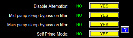
Image 1.7
- Disable Alternation: Enable or disable pump alternation. Selecting "Yes" disables the alternation configuration options and causes pumps to alternate only when a fault condition triggers alternation. Selecting "No" restores the alternation configuration controls.
- Mid pump sleep bypass on filter: If selected yes,
- Main pump sleep bypass on filter: If selected yes,
- Self Prime Mode: For suction‑lift stations, wet switches are normally provided to confirm pump volutes contain water before starting—typically used with a primer pump. If no primer pump is installed, enable Self‑Prime mode for stations equipped with self‑priming pumps.
- Self‑Prime = Yes: The PLC will start the pump without requiring a wet‑switch signal, allowing the self‑priming pump to develop suction and lift water from the sump.
- Self‑Prime = No: The PLC will start the priming pump and wait for the wet switches to indicate water presence at the pump head before starting the main pump.
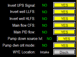
Image 1.8
- Invert UPS Signal: This setting inverts the UPS signal the PLC monitors for loss of supply power. Configure the polarity to match the UPS wiring so the PLC correctly detects mains loss and remains powered long enough to send shutdown alerts. If misconfigured, the PLC may not stay awake to report UPS/low‑voltage events.
- Invert Well LLFS and HLFS: Specify the orientation of the well float switches to match the physical devices (Normally Open or Normally Closed). Ensure the configured polarity on this screen matches the installed float wiring so the PLC interprets the signals correctly.
- Main Flow CFS: The factory default flow unit is GPM. If preferred, you can configure the system to display flow in CFS (cubic feet per second) instead. CFS represents the volumetric flow rate as cubic feet per second rather than gallons per minute.
- Main PID Flow: Normal PID uses discharge pressure as the control variable—this provides stable, pressure‑based delivery. If your application requires maintaining a target flow instead of pressure, switch the PID mode to Flow. In Flow PID the flow‑meter reading becomes the process variable and the VFD adjusts motor speed to maintain the configured flow setpoint.
- Pump Down Source Level: Enabling Pump‑Down mode converts the station from a pressure‑maintenance system to a pump‑down system. In this mode the station will operate until the configured cut‑in and cut‑out level setpoints are reached and may use level‑based sleep logic instead of pressure or flow. Configuration options and control logic are adjusted accordingly to support pump‑down operation.
- Pump down Critical Mode: Pump‑Down Critical Mode is a special, high‑risk operating mode intended for emergency use only. Unlike standard Pump‑Down operation, which uses the Source LLFS to stop pumps before the source runs dry, Critical Mode ignores float switch status and forces the pumps to run continuously. Pumps will only stop if taken out of AUTO or manually disabled.
- The pump speed is also controlled via the control variable and not the manual speed reference from either the screen, or the speed potentiometer.
- Do not enable this mode unless you are actively supervising the station and understand the risk of running the source dry. Use only for controlled emergency drains; manual intervention is required to prevent pump damage.
- WYE Location: A WYE strainer may be installed on either the intake or discharge side of the pump station. Omnia monitors pressure upstream and downstream of the strainer (regardless of location) to detect differential pressure and trigger cleaning.
- Intake‑side configuration: automation compares the Pre‑WYE (upstream) transmitter to the Intake (downstream) transmitter.
- Discharge‑side configuration: automation compares the Pre‑WYE (upstream) transmitter to the Discharge (downstream) transmitter.
|
|
¶ Voltage Good and Bad Delay
When a voltage monitor is installed, the PLC applies short filter timers to ignore brief supply transients. If the incoming power is particularly unstable, these timer delays can be extended to allow the voltage monitor to confirm stable power before the system proceeds with startup. This prevents drives and sensitive components from energizing during poor supply conditions, improving protection and reliability.

¶ Low PSI Switch
If the panel is configured with a discharge pressure switch instead of an analog transmitter, we can configure the digital signal from the switch to the PLC as N.O. or N.C. (image 2.0).

¶ Filter Group Config
Filter group config (image 1.1) applies to stations equipped with multiple filters and PSID switches. Rather than wiring each PSID to a separate PLC input—which can cause frequent, isolated flush cycles—Omnia allows grouping of PSID signals into a single input. When any filter in the group triggers, the system initiates a coordinated flush of all filters in that group. This approach reduces unnecessary cycling and ensures that filters cleaned individually are refreshed simultaneously, since a single triggered filter typically indicates the others are nearing the same condition.
For stations with more than three filters, consider the total time required to flush the entire group; use the filter group settings to sequence and space flushes appropriately to avoid excessive run times or system strain.

¶ Filter Group Configuration
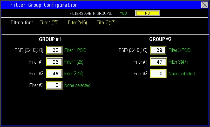
Filter Group Configuration (Image 1.2)
This screen lets you assign filters to one or two PSID‑triggered groups so multiple filters can be flushed together.
How to configure:
- Filters Are In Groups: Select Yes to enable two filter groups; select No to use a single group.
- Filter Options: Reference list of filter ID codes used to identify individual filters and PSID inputs.
- Group #1 & Group #2 Configuration:
- Assign each group a PSID input to monitor (select the PSID code the group will follow).
- Example: Group 1 follows PSID Filter #1 (code 32); Group 2 follows PSID Filter #3 (code 39).
- Assign Filters to Groups:
- Select which filter IDs will be included in each group (use the Filter Options codes).
- Example: Group 1 includes Filter #1 (code 25) and Filter #2 (code 46) and is triggered by PSID code 32. Group 2 includes Filter #3 (code 47) and is triggered by PSID code 39.
- A fourth filter, if present, may be assigned to either group as required.
Grouping PSID inputs reduces unnecessary individual flush cycles by cleaning multiple filters when one shows high differential pressure.
¶ SCADA Config
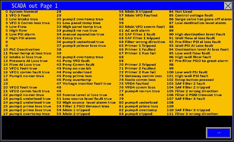
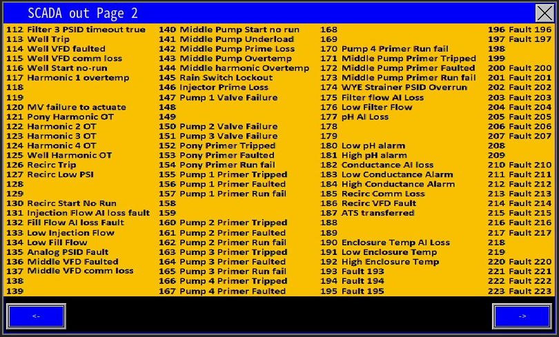
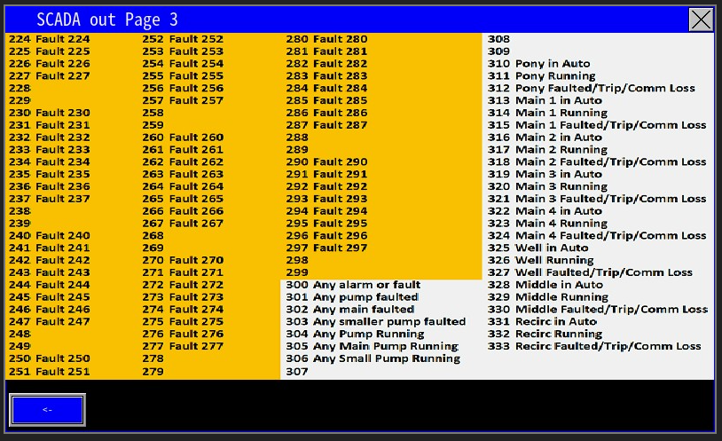
The SCADA Config screen is used to assign the correct digital output signals to the SCADA system (image 1.1).

From the SCADA Config screen (Image 1.2), display available outputs and assign each to a SCADA output bit. Click Help to show the full output list (Images 1.3–1.5), locate the desired output, then enter its reference code into the Value field to complete the assignment.
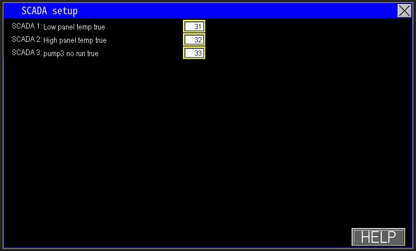
List of the SCADA outputs that are configurable
|
|
|
¶ Well PID Config
The Well PID Configuration (image 1.1) defines how the well pump is controlled and directly determines which options and controls appear on the Well Pump settings page. Choices made here affect runtime behavior, available automation modes, and the control parameters accessible on the back end—so configure this section to match the installed equipment and intended operation (image 1.2).

|
|
¶ Well PID process
Select the Well PID process (image 1.3) that matches the pump’s intended operation. This choice is the most critical configuration step, as it determines the control strategy, available automation options, and the settings exposed on the Well Pump settings and back‑end program. Choose the PID process that reflects how the well will be used to ensure correct automation behavior. Utilize the help page to help determine this automation process and input the code to implement that process (image 1.4).

|
|
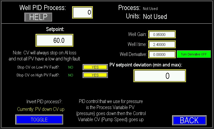
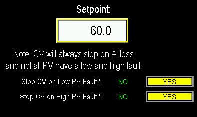
¶ Select the Well PID Process and Setpoint (Image 1.5)
Choose the Well PID process that matches the pump’s intended operation. This determines the control strategy and which automation options and settings will be available throughout the Well Pump configuration.
Specify the control setpoint (Process Variable). Depending on the selected PID process, the setpoint may be expressed in PSI, flow (GPM), pH, PPM, temperature, or another engineering unit.
Clarifications:
- CV (Control Variable) — the speed or speed reference sent to the pump (the output).
- PV (Process Variable) — the measured value the controller is trying to maintain (e.g., pressure, flow).
Note: “CV will always stop on AI loss” means if the PV transmitter fails (analog input loss), the controller will stop the CV because it no longer has a reference to control against.
Low/High PV Fault Behavior:
- Not all PVs support both low and high fault actions. The Low/High fault action settings let you choose whether a PV fault should cause the pump to continue running or to shut down. Configure these responses according to the criticality of the monitored PV.
¶ PID adjustments
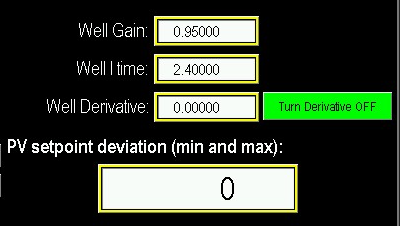
PID Adjustments (Image 1.6)
These parameters tune how the controller responds to changes in the process variable (PV) to achieve stable, smooth pump operation:
Gain (Proportional): Determines how strongly the output responds to the instantaneous error (setpoint − PV). Higher gain yields faster response but increases risk of oscillation; lower gain reduces overshoot but slows response.
Integration (I‑Time): Governs how quickly accumulated steady‑state error is corrected. Increasing integration speeds correction but may introduce overshoot; decreasing slows long‑term correction.
Derivative (D): Reacts to the rate of change of the PV to dampen fast disturbances. Higher derivative improves response to rapid changes; lower derivative reduces sensitivity to noise.
PV Setpoint Deviation (Deadband): Sets the deviation range around the setpoint within which the controller is less reactive. Smaller deadband increases responsiveness to small errors; larger deadband smooths minor fluctuations.
Adjust these settings iteratively: start with conservative (lower) gain and integration, enable minor derivative if needed, and adjust and deadband to balance responsiveness with stability and equipment wear.
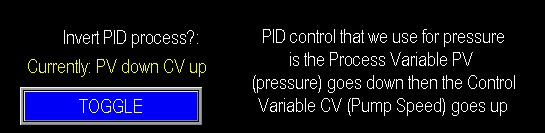
¶ Invert PID Process
By default, this program reduces the control output (CV) as the process variable (PV) increases—i.e., higher PV → lower CV. If your application requires the opposite behavior, you can invert the control direction so that the CV increases as the PV rises. Configure this option to match the intended operational design of the station by pressing the toggle button (image 1.7).
Example — Inverting Control Direction
Scenario: A well pump controls tank level (PV) by adjusting pump speed (CV).
Default (Higher PV → Lower CV)
- Setpoint: 50" level
- Behavior: As tank level rises above setpoint, the pump slows to avoid overfilling.
- Example: PV = 55" → CV reduces from 60% to 30% to lower inflow.
Inverted (Higher PV → Higher CV)
- Use case: A recirculation process where higher measured conductivity (PV) requires increased agitation (CV).
- Behavior: As PV rises, the pump speeds up.
- Example: Setpoint: 200 µS; PV = 250 µS → CV increases from 40% to 70% to boost recirculation.
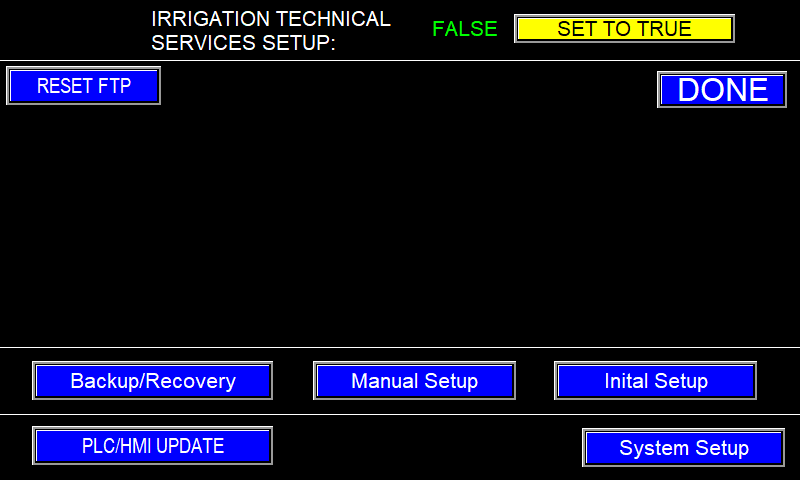
¶ Irrigation Technical Services Setup (Feature only applies to this company)
When "Irrigation Technical Services Setup" is set to True, ITS features are enabled and can be accessed by the ITS password. This unlocks advanced filter and fill‑device options, including the ITS Retro Filters capability on System Setup Screen 2.
Key points:
- Standard Omnia supports up to three filters; enabling ITS allows expanded, custom configurations with additional filters and flush valves.
- For non‑ITS systems, use Filter Grouping to assign filters to PSID groups so multiple filters can be flushed together based on grouped PSID inputs.
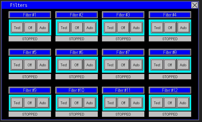
- ITS bypasses the normal Filter Grouping UI: it automatically groups all filters so they can be flushed from a single PSID input, supporting up to 12 flush valves.
- ITS features are highly customizable and intended exclusively for ITS panels.
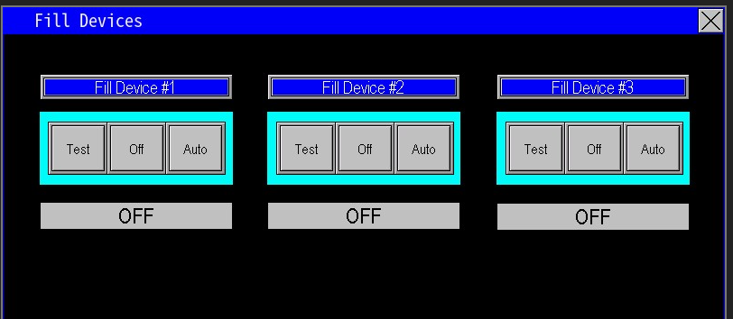
- Enabling this will also group the fill devices into one fill device group as well.
- Examples on image 1.3.
- Applicable only to hydraulically driven filters; motor‑driven filters are not supported.

|

|
|
|
|
When you open “Filters” or “Fill Devices,” the screen displays all filters or fill devices currently configured on the panel (image 1.4 & image 1.5).
¶ ITS Password
When ITS is enabled, ITS personnel use the password IRRTECH2 to access ITS‑level administrative settings on the panel.
¶ ASP Password
ASP (Area Service Provider) Access
ASP access is preconfigured for each job. The default ASP password is ASP01PPS.
PPS can revoke this password at any time to restrict administrative access to the panel.
D20812.00 ASP Password enable/disable
¶ Backup/Recovery
The Backup Management screen (image 1.1) lets you save and restore factory configuration data. Use this feature as a fail‑safe during service calls: if on‑site troubleshooting cannot resolve an issue, loading the factory calibration will restore all parameters to their original factory settings, enabling a known good baseline for further diagnostics.
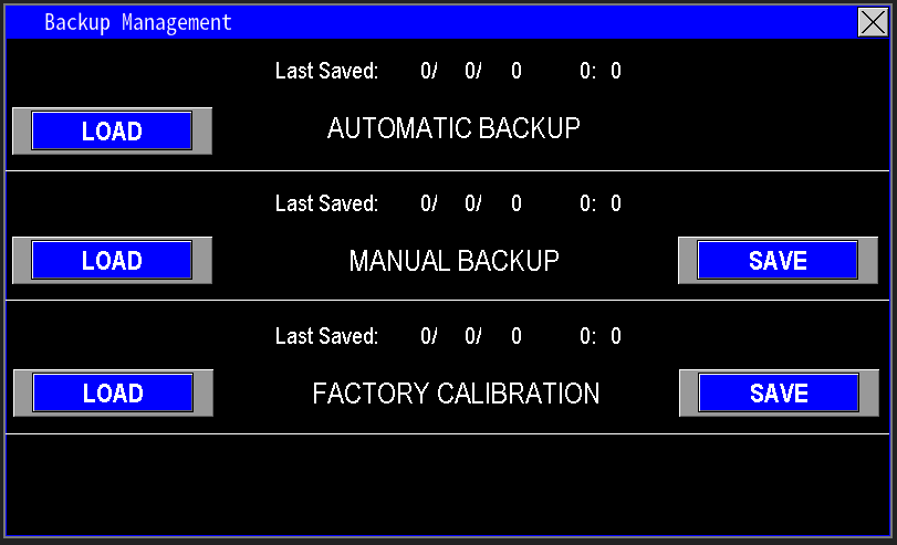
The Backup Management screen provides three save slots for storing configuration data. Use these slots to save known‑good configurations for quick restoration during troubleshooting or service.
¶ Automatic Backup:
The automatic backup captures and saves parameter changes made while the station is running. When external conditions require tuning, those adjustments are stored automatically so the station retains its current configuration. In the event of a power outage, the automatic backup ensures the station restarts with the same parameters and operating state as before the interruption.
¶ Manual Backup:
Manual Backup is a password‑protected save intended for verified, field‑tested configurations. The factory calibration contains default motor parameters and setpoints chosen during factory testing. After the panel is installed and commissioning is complete, create a Manual Backup to capture the exact configuration verified on site. This provides a reliable restore point representing the tested pump‑station and panel combination, useful for future troubleshooting or recovery.
¶ Factory Calibration:
During factory testing the panel is configured with the parameters specified on the original work order — the settings used to validate correct operation. If the station becomes unstable, settings are corrupted, or parameters are lost after a power event, performing a Factory Load restores the panel to those original, factory‑verified settings so the system returns to its baseline configuration.
¶ Manual Setup
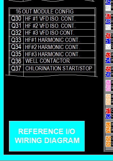
If an FCData file or SD card is unavailable, you can manually configure the I/O map. Build the I/O map by following the panel schematic and the I/O callouts (Image 1.1). Trace each wire on the schematic to the corresponding PLC input or output to identify where every device is connected.
Manual mapping takes a bit longer but is straightforward and preferred when adding or updating components—use this method to integrate new devices into the I/O configuration reliably.
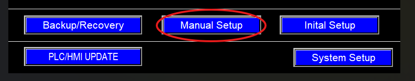
If the Admin page is not prepopulated at first startup—or you need to add a new component—open the Admin screen and enter the administrator password. Then select Manual Setup (Image 1.2) to open the Manual Setup dialog (Image 1.3) and proceed with I/O configuration.
|
|
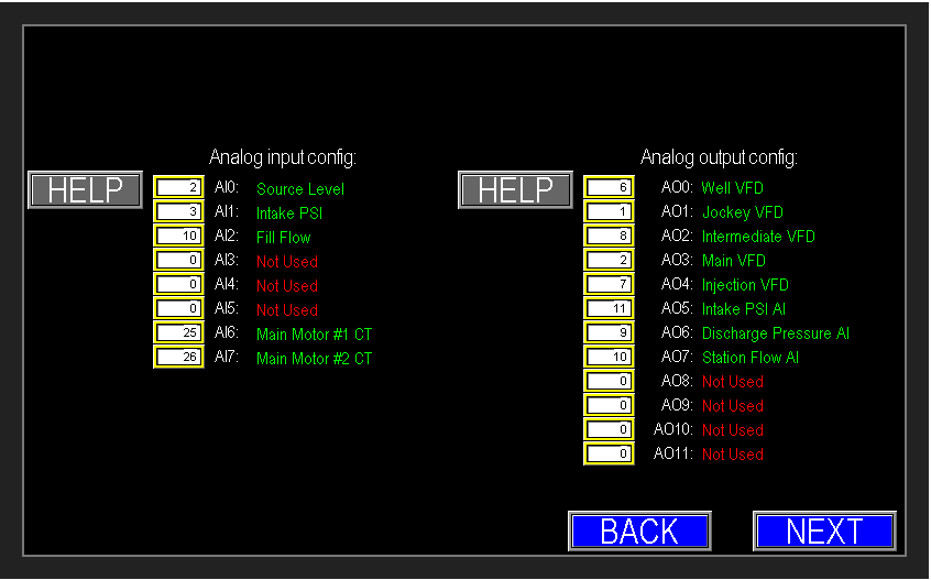
Analog I/O Mapping (Manual Setup)
- Refer to the panel schematic to locate sensor wiring and identify the corresponding PLC analog channel.
- Enter that channel number into the matching Analog Input/Output field. If adding a new device, use the next unused channel.
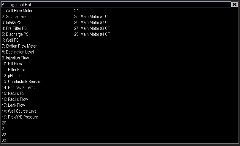
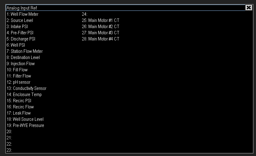
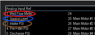
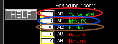
- Use the Help button beside each field to display the channel reference list ( Image 1.4).
- Verify mappings against the Help cross‑reference (example: Analog inputs 0, 1, 2 are mapped as shown in (Image 1.5 & 1.6 ).
|
|
|
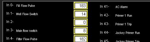
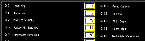
Analog outputs (Image 1.7), digital inputs (Image 1.8), and digital outputs (Image 1.9) are configured the same way. Refer to the panel schematic and enter each I/O in the sequence shown on the I/O callout (Image 1.1). Use the Help reference where available to verify channel assignments.

|
|
|
IO configuration is completed.
¶ PLC/HMI Update
Omnia is continuously improved with new features and enhancements. To ensure field panels benefit from the latest functionality, update the panel software when a new release is available. Ensure the panel’s modem has a reliable internet connection before proceeding.
To begin, open the PLC/HMI Update screen from the Admin menu or the main Menu (Image 1.1). Follow the on‑screen prompts to download and apply the update.

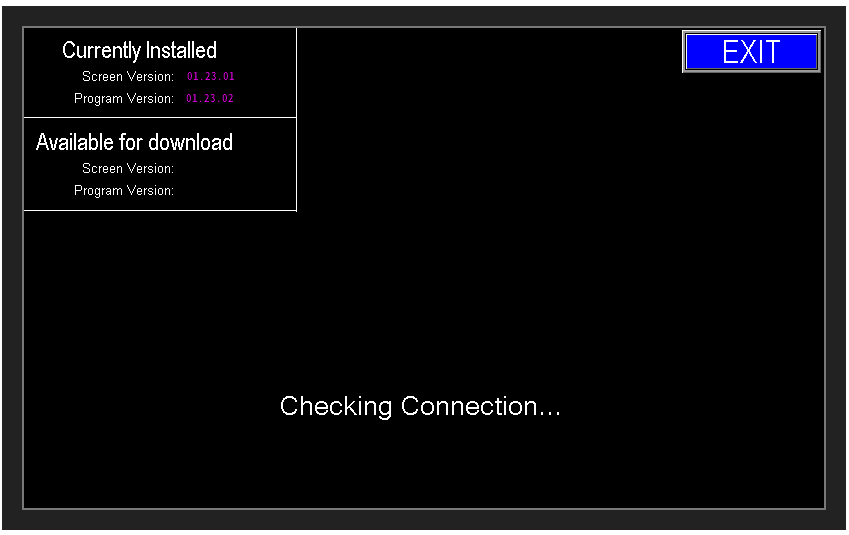
After opening the PLC/HMI Update page, the update interface will load (Image 1.2). If the panel lacks a working internet connection, the update attempt will fail and the screen will indicate a connection error (Image 1.3). Ensure the panel’s modem and network are functioning before attempting an update.
|

|
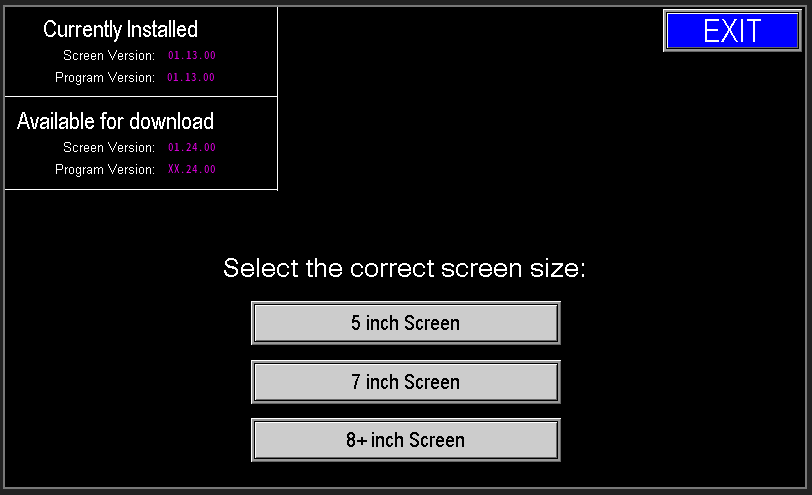
Once the panel is online, the update interface lists the latest available PLC and HMI releases. Download one update at a time:
- Insert a USB flash drive into the panel USB port when prompted (image 1.4).
- For HMI updates, choose the correct screen size (8" or 8+") (image 1.5).
- Click Download Update — the update files will be written to the USB drive (screen will indicate progress) (image 1.6).

|
|
|
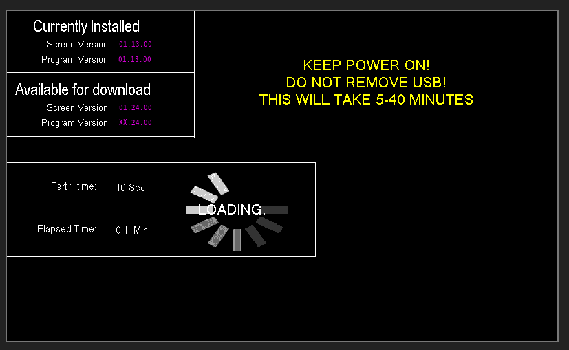
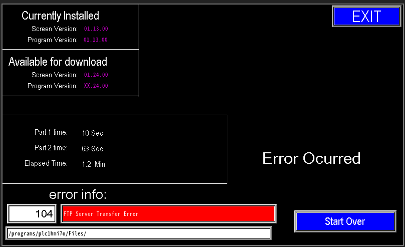
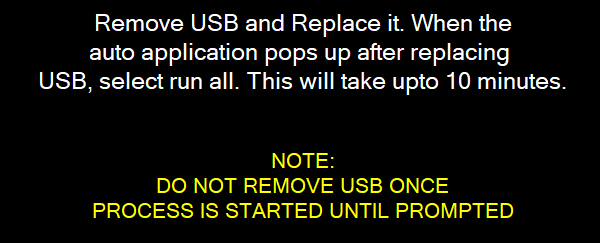
Download time varies with the panel’s internet connection (image 1.7). Keep the panel powered and the USB drive inserted for the entire download (Image 1.8). When the download finishes, the screen will prompt you to remove and reinsert the USB (image 2.0). If the download fails, the Error Info screen will display—verify the internet connection and retry.

|
 |
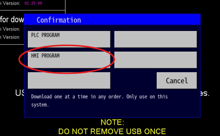
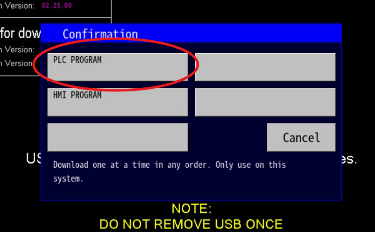
Once the download completes, the interface will prompt you to remove and reinsert the USB drive (Image 2.0). After reinserting, the downloaded update files will be displayed on the screen:
- HMI Program (Image 2.1).
- PLC Program (Image 2.2).
|
|
|
|
During an HMI update the PLC remains operational, but the HMI touchscreen is temporarily unavailable until the update completes. During a PLC update the station is taken offline and both the PLC and HMI are unavailable until the update finishes.
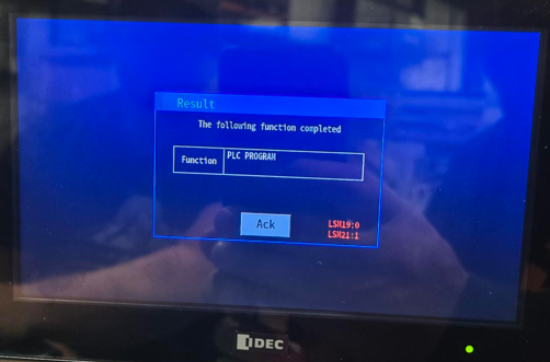
A progress bar displays download status while the update is in progress (image 2.3).
When complete, the screen will indicate which update(s) succeeded (image 2.4).
|
|
|
After the download completes, remove the update files from the USB drive to prevent accidental reuse and reduce the risk of file‑transfer errors in future operations.
¶ Activation
Activation enables full automated operation of the station. Once activated, the end user has unrestricted access to all system functions.
If the station is not activated, it runs in Demo mode: full functionality is available for a limited trial period. After the trial expires the station becomes inoperable and the PLC locks out until a valid activation code is entered.
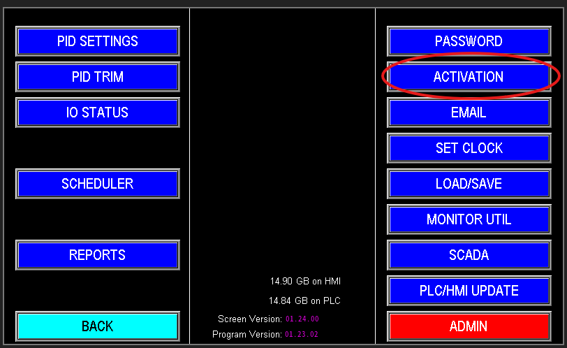
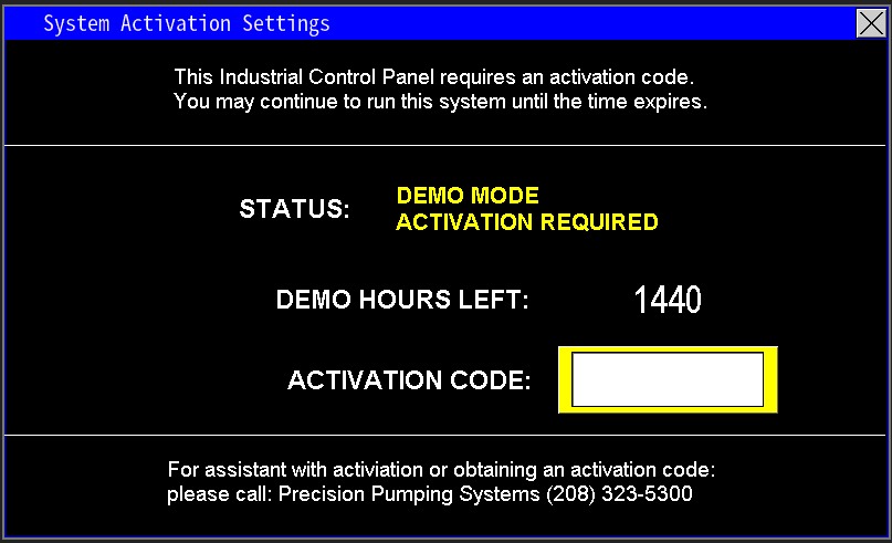
Open the Activation tab to view the panel’s current state: Demo Mode, Expired, or Activated (image 1.2).
Demo Mode indicates the panel is operating on a trial basis (for example, pending payment). In Demo Mode the station remains fully functional for a limited period (1440 hours). The screen displays the remaining trial time. When the trial expires, automatic functions are disabled and the PLC requires a valid activation code to restore full operation.
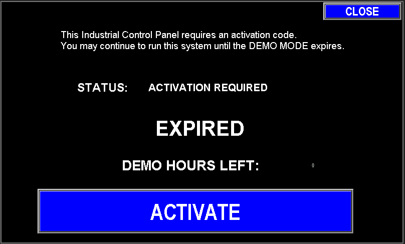
When Demo Mode expires, the system displays an expiration notice (Image 1.3). All automatic functions are disabled until the panel is reactivated by entering a valid activation code.
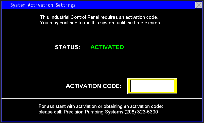
If Demo Mode must be extended, use demo code 358. To activate the station, enter the work order number (typically six digits).
If the work order does not activate the panel, go to Admin → System Setup and check the Activation Code field (Image 1.4). If the activation code was changed contact PPS to find out why. If for no reason at all, restore it to the proper code for the panel.
Once the correct activation code is entered, the screen will display “Activated” (Image 1.5).

|
|
¶ Troubleshooting Admin Settings
Troubleshooting I/O SD Card factory load settings
Troubleshoot System Error Code on Main Page