¶ Filter Flow Meter
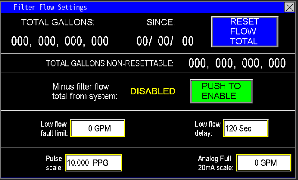
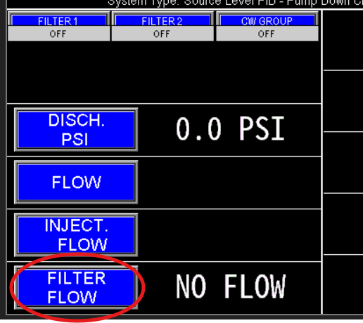
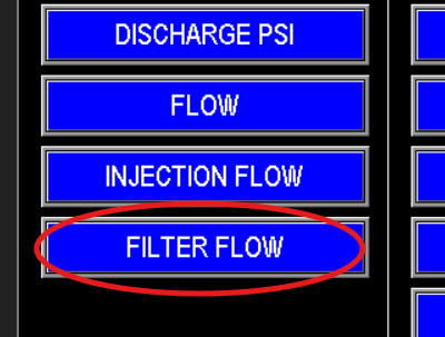
The filter flow meter monitors the volume of water used to flush the filter. You can access and view this data (image 1.1), as well as configure related automation, either through the main screen (Image 1.2) or via the menu screen (Image 1.3).
|
|
|
¶ Filter Filter Flow Data
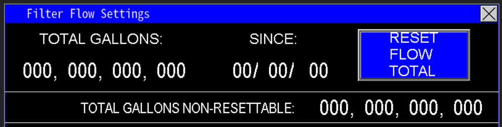
At the top of the screen (Image 1.4), the PLC displays real-time data collected from the filter flow meter, specifically the total gallons used for filter flushing. The "since" date indicates the last reset point; pressing the "Reset Flow Total" button will reset the gallons counter to zero and update the "since" date to the current date on the HMI.
Additionally, the Total Gallons Non-Resettable totalizer continuously records the overall volume of water used for filter cleaning since system installation or the last hardware reset. This total cannot be cleared or reset by the user.
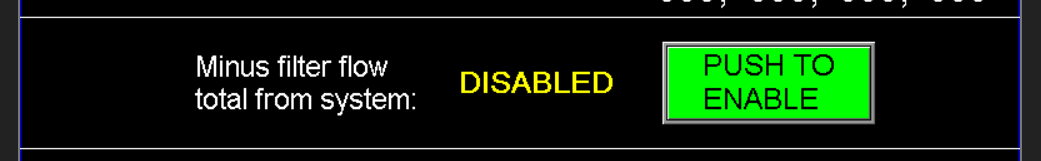
¶ Minus fill flow total from system
Typically, the filter flow meter is installed on the discharge side of the pumps before the station flow meter. However, in some applications, the filter may be positioned after the station flow meter. To ensure accurate measurement of the water delivered to the rest of the watering system, the volume recorded by the filter flow meter can be subtracted from the station flow meter's total flow (image 1.5). This adjustment corrects the totals for daily, monthly, and yearly reports, preventing overestimation caused by the filter’s placement.
¶ Low Flow Fault Limit and Delay
The low fault limit is a user-defined threshold used to monitor whether the filter flush valve is receiving sufficient flow for effective cleaning (image 1.6). If the flow measured by the filter flow meter drops below this limit, the system initiates a delay timer. During this delay, the station continues to operate at or below the fault threshold, allowing time for air pockets to clear or valves to fully open and close. If the low flow condition persists beyond the delay period, the system will generate a fault, signaling that the filter isn't getting adequate water flow for proper cleaning.

¶ Pulse Scale and Analog Full 20mA scale
Omnia supports monitoring station, fill, recirc, and well flow meters that output pulse or analog mA signals. For pulse meters, follow the manufacturer's instructions to determine the flow meter’s k‑factor (pulses per gallon). Enter this value into the Pulse Scale setting.
Next, zero the mA Scale—this activates the pulse measurement mode. If the mA scale is not zeroed, pulse readings will not function correctly. Once configured, the system converts incoming pulses into flow rates, displaying the flow in GPM on the main screen of the HMI (Image 1.7).
The Analog Full 20mA Scale should be set to match the maximum flow rating of the flow meter’s 20mA output. This value typically represents the highest flow the meter is rated to measure. For meters with adjustable 20mA span, verify that this scale matches the configured maximum output value on the flow meter to ensure accurate readings and proper system calibration.