¶ Discharge Pressure Settings
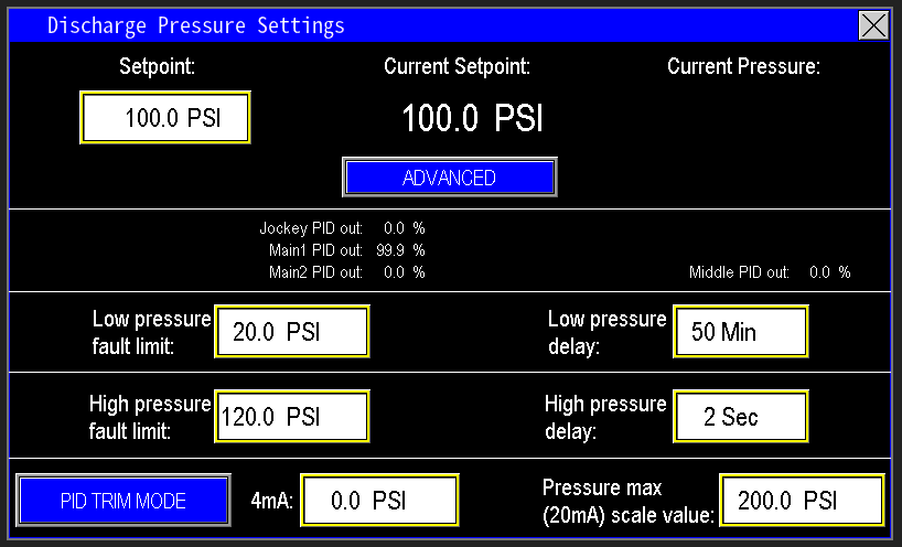
Discharge pressure (image 1.1) is the primary control parameter for most station operations in Omnia. The automation system monitors the discharge pressure transmitter and adjusts pump operation to maintain the required pressure setpoint for the application.
Setpoints
- The setpoint is the target pressure the station must maintain.
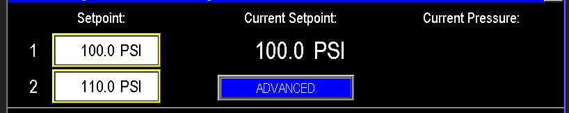
- Some systems include two setpoints to allow the same pump arrangement to operate at different pressure zones or schedules (Image 1.2).
|
|
When Setpoint 2 is configured, an external input is typically wired to the station. When the PLC detects that input, it switches the station to Setpoint 2 and operates the pumps at that secondary pressure.
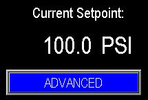
¶ Current Setpoint and current pressure
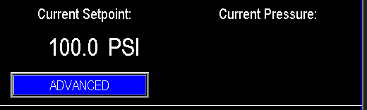
The Current Setpoint reading shows the pressure the station is presently running at (image 1.3). Under normal operation this will match the station’s configured setpoint. However, when the station is operating in Level PID, Intake PID, or Fill Mode, the current setpoint may differ from the configured value.
Use this display as a diagnostic reference: if the station is not operating at its configured setpoint, the Current Setpoint indicates whether the PLC has reduced motor speeds due to one of the modes or control actions described above.
¶ Pump PID Output
Below the setpoint values is a readout of the PLC’s PID output to the drives (image 1.4), scaled as a percentage. This value represents the commanded drive speed (e.g., a PID output of 50% commands the drive to run at half speed). Use this readout to monitor station performance, refine precise PSI setpoints, and troubleshoot issues. In the example shown, the PLC is commanding the Main1 drive to run at 100% (full speed).

¶ Low pressure fault limit and delay
The Low Pressure Fault Limit and Delay configure when the station will fault for low discharge pressure (image 1.5). Set the fault limit to the minimum acceptable discharge pressure and set the delay to accommodate the time the system typically needs to build pressure.
- Use site demand and historical fill times to choose appropriate values so the station is not faulted during normal startup.
- If the system cannot reach the configured pressure before the delay elapses, the station will fault, indicating a problem requiring inspection (e.g., pump issue, open zone/valve, or piping failure).
- When in Fill Mode, the station will not fault till it comes out of fill mode and hits setpoint. At which point, if the pressure falls back below the low pressure fault limit, then it will fault after the delay timer elapses.

¶ High pressure fault limit and delay
The High Pressure Fault Limit and Delay operate like their low-pressure counterparts but are configured to trigger much faster—typically within a few seconds—to protect system components (image 1.6). Set the high-pressure limit at or below the weakest component’s maximum allowable PSI to prevent damage. When the measured discharge pressure exceeds this limit, the station should fault and shut down immediately to protect the system.

¶ Discharge PSI min (4mA) scale value and max (20mA) scale value (Transmitter scaling)
The PSI Min and Max scale values define the pressure range corresponding to the transmitter output on the discharge (image 1.7). Enter the pressure that corresponds to the transmitter’s 4 mA output as the Min (4 mA) scale value, and the pressure that corresponds to the 20 mA output as the Max (20 mA) scale value. These adjustable ranges allow replacement with transmitters of different span without requiring PLC reprogramming.
¶ PID trim mode
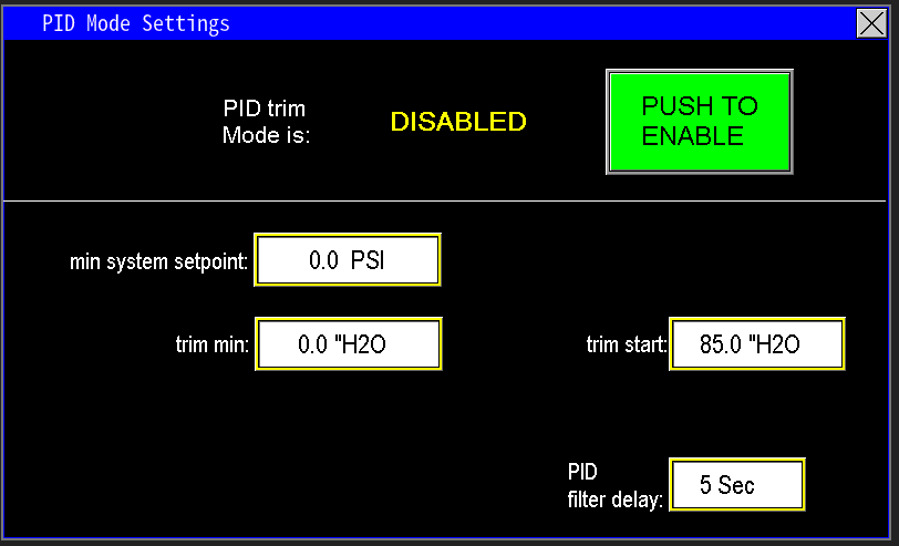
PID Trim Mode adjusts the station setpoint based on reduced source water levels (image 1.8), extending pump run time when levels fall. A level transmitter on the pump station is required for this feature.
When the station repeatedly faults on low-level conditions, PID Trim scales down pump speeds as the level declines, allowing the station to continue supplying flow rather than immediately tripping.

|
|
When PID Trim Mode is enabled, the station scales the discharge setpoint to reduce motor speed as source water levels decline.
- Minimum System Setpoint (Image 2.0): the lowest discharge pressure setpoint the station will operate at. Once the scaled setpoint reaches this minimum, the pump will run at that speed until a low-level fault occurs.
- Trim Start and Trim Min (Image 2.1): define the level-based scaling range.
- Trim Start: the source level at which the PLC begins reducing the discharge setpoint.
- Trim Min: the minimum source level at which the pumps should continue to operate.
Example: If Trim Start is set at 85" H2O and the configured setpoint is 100 psi, the PLC will begin decreasing the current setpoint at 85" and progressively scale the setpoint down until it reaches the Minimum System Setpoint.
The PID Filter Delay (image 2.2) defines how often the station applies successive setpoint adjustments. When PID Trim conditions are active, the station updates the discharge setpoint at the configured interval (for example, every 5 seconds) until either a low-level fault occurs or source levels return to normal.

|

|

|
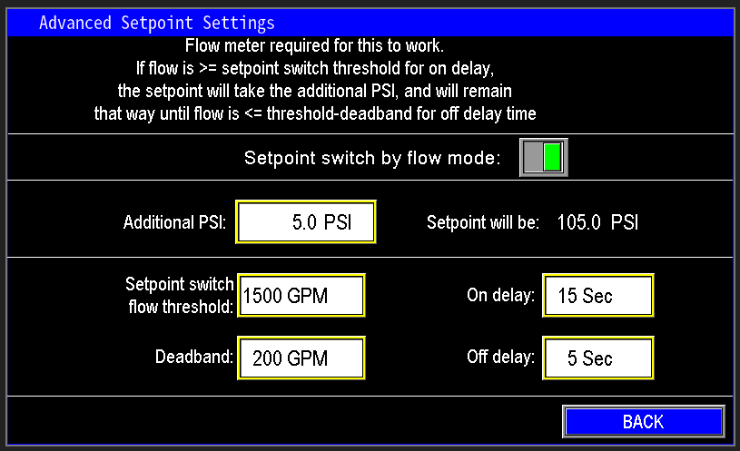
¶ Advanced Setpoint Settings
Selecting the Advanced button (Image 2.3) opens the Advanced Setpoint screen (Image 2.4). This screen provides additional control features in Omnia to optimize pump station performance. A flow meter is required for these advanced features to function.
This feature raises station discharge pressure based on measured flow to compensate for pressure loss in long or valve-heavy discharge lines. When enabled and configured, the Advanced Setpoint settings increase the discharge setpoint as flow increases, offsetting friction losses so adequate pressure is maintained at the line extremities.
|
|
¶ Additional PSI
To use this function, measure pressure at the end of the line. In the example (image 2.5), the station discharge is 100 psi while the affected zone reads 95 psi — a 5 psi loss. Enter the additional PSI value (5 psi) in the Advanced settings. The station setpoint will increase to 105 psi, delivering approximately 100 psi at the line end to compensate for the loss.

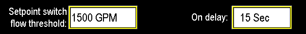
¶ Setpoint switch threshold and Deadband
The Setpoint Switch Flow Threshold (image 2.6) defines when the flow-based pressure compensation activates. It requires a flow meter.
Example:
- Condition: flow ≥ 1500 GPM for longer than 15 seconds.
- Action: add the configured PSI offset (e.g., +5 PSI) to the discharge setpoint.
- Result: PLC increases pump speed until the discharge transmitter reads the new setpoint (e.g., 105 PSI), compensating for the downstream pressure loss.
|

|
The Deadband defines when the advanced flow-based pressure boost is turned off (image 2.7). It specifies the reduction in flow the meter must detect for the feature to deactivate.
Example:
- Setpoint Switch Threshold: 1500 GPM
- Deadband: 200 GPM below threshold → 1300 GPM
- Time qualifier: flow must remain below 1300 GPM for longer than 5 seconds
When this condition is met, the additional PSI boost is removed and the station returns to the normal discharge setpoint (e.g., 100 PSI).