¶ Fill Flow Meter Settings
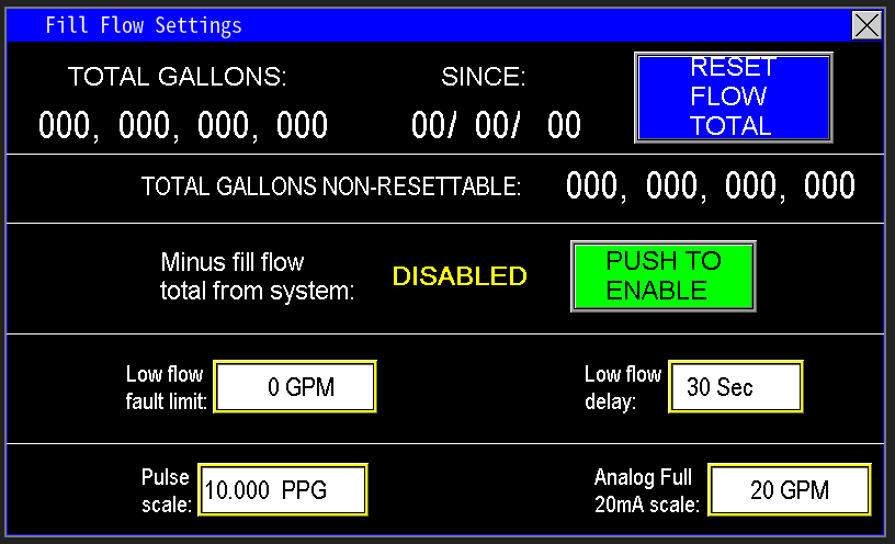
Fill flow settings pertain to the system section controlled by the fill device (image 1.1). In many applications within Omnia and on pump stations, a flow meter may be used with the fill device to accurately monitor the volume of water diverted from the main flow. These settings enable tracking of the flow rate through the fill device, allowing precise measurement of water diverted, ensuring effective control and monitoring of the fill process.
The Fill flow meter pertains to water flowing through the fill valve.
¶ Total Gallons
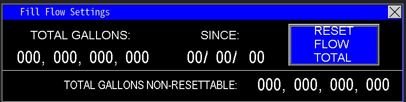
The total gallons display shows the cumulative volume of water that has passed through the fill device flow meter since the date shown on the right side of the screen (image 1.2). This total is resettable; pressing the Reset Total button will reset the gallon count to zero and update the date to the current date displayed on the HMI.
This totalizer records the cumulative volume of water that has passed through the fill device since installation. It continually counts and cannot be reset, providing an ongoing record of total flow over the system’s lifetime.
¶ Minus fill flow total from system
The placement of the fill device relative to the station flow meter can impact the accuracy of flow measurements, leading to discrepancies in total station flow. To correct this, the flow measured by the fill device (fill flow meter) can be subtracted from the station's total flow (GPM). This adjustment ensures the calculated totals—daily, monthly, and yearly—accurately reflect the water delivered to the watering system, eliminating overestimates caused by the fill device’s position or other factors (image 1.3).

¶ Low Flow Fault Limit and Delay
This feature enables the user to set a flow threshold to monitor the efficiency of the fill line and ensure it is receiving sufficient water (image 1.4). When the flow drops below the set fault limit, the system activates an alarm to alert that the fill line may be underperforming. The delay period allows the system to continue operating at or below this limit for a specified duration, providing time for air pockets to clear or valves to fully open or close before the system faults. This prevents false alarms and ensures accurate monitoring of fill line performance.

¶ Pulse Scale and Analog Full 20mA scale
Omnia supports monitoring station, fill, recirc, and well flow meters that output pulse or analog mA signals. For pulse meters, follow the manufacturer's instructions to determine the flow meter’s k‑factor (pulses per gallon). Enter this value into the Pulse Scale setting.
Next, zero the mA Scale—this activates the pulse measurement mode. If the mA scale is not zeroed, pulse readings will not function correctly. Once configured, the system converts incoming pulses into flow rates, displaying the flow in GPM on the main screen of the HMI (Image 1.6).
The Analog Full 20mA Scale should be set to match the maximum flow rating of the flow meter’s 20mA output. This value typically represents the highest flow the meter is rated to measure. For meters with adjustable 20mA span, verify that this scale matches the configured maximum output value on the flow meter to ensure accurate readings and proper system calibration.

|

|