¶ SCADA
SCADA provides communication and supervisory control across distributed controllers and sites (image 1.1). It enables controllers to share status and process data so systems that depend on remote inputs can operate correctly. Use the SCADA configuration to establish connections, map required tags between controllers, and ensure reliable data exchange for monitoring and coordinated control.
¶ SCADA Settings
On the SCADA screen is where this communication is set up, and we will go over what some of these options do (image 1.2).
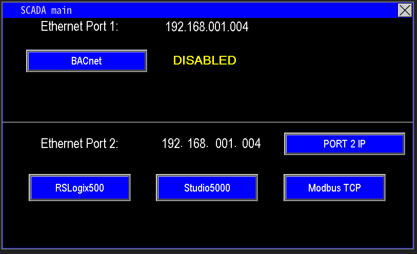
¶ BACnet (Ethernet Port 1)
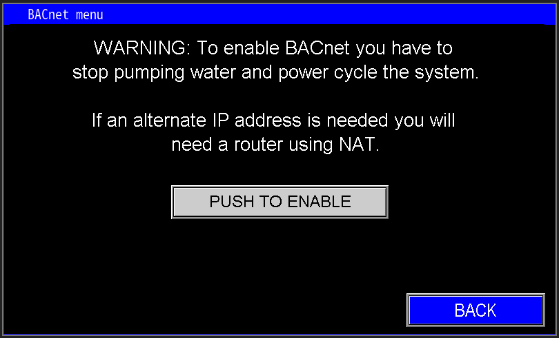
BACnet (Building Automation and Control Network) is an open communication protocol that enables interoperability between automation systems from different manufacturers. Enabling BACnet opens a gateway for data exchange between Omnia and other BACnet‑compatible controllers (image 1.3).
To configure BACnet in Omnia, enter the BACnet settings screen and follow the on‑screen instructions shown in Image 1.4 to enable and set up the BACnet features.
|
|
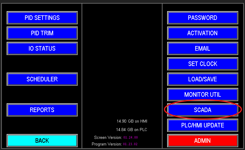
¶ RSLogix500, Studio5000, and Modbus TCP (Ethernet Port 2)
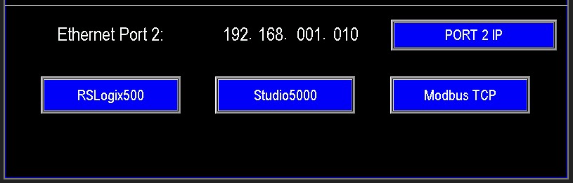
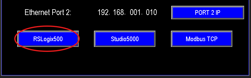
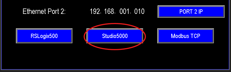
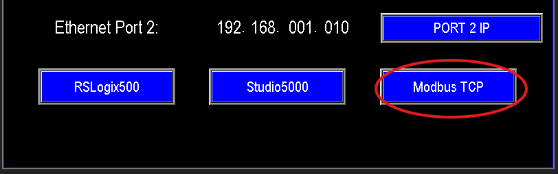
This section (image 1.5) configures how the panel exposes data to SCADA:
- Port 2 IP: sets the fixed IP address used for SCADA communication on Ethernet port 2.
- RSLogix500 / Studio5000 / Modbus TCP buttons: display the register/address mappings and protocol specifics SCADA systems should use to read tags from this panel.
Use these mappings to point your SCADA or PLC program to the correct registers and network endpoint for reliable data exchange.
¶ Ethernet Port 2
The standard with PPS is to use 192.168.1.4 as the PLC IP address. Port needs to change, enter into the port 2 screen (image 1.5).
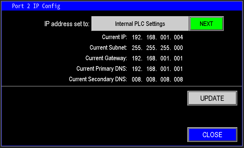
When you open the SCADA network screen you have three configuration modes:
- Internal PLC Settings (Image 1.6): uses the PLC’s built‑in Ethernet settings for communication.
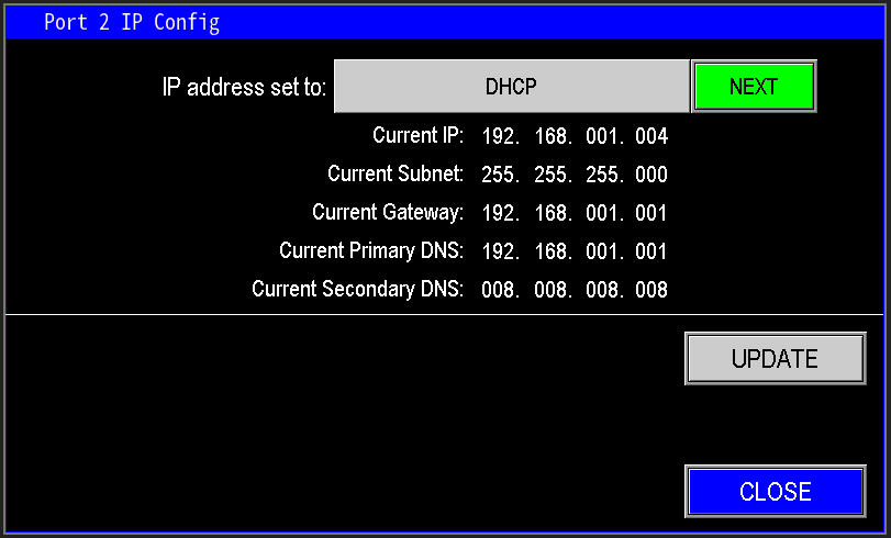
- Dynamic IP (DHCP) (Image 1.7): lets Port 2 obtain an IP automatically from the network DHCP server so the panel takes an available dynamic address.
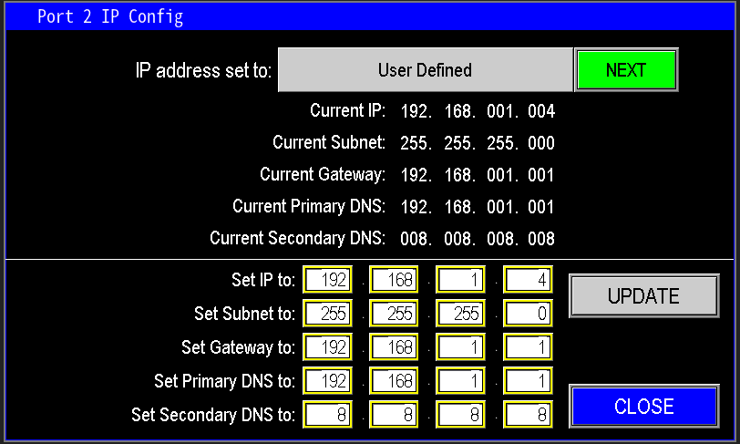
- User‑Defined (Static) (Image 1.8): lets you specify a fixed IP address for Port 2. Use this when a static address is required for SCADA connectivity.
Notes:
- Use DHCP for ease of integration when your network supports dynamic addressing.
- Use User‑Defined (static) when SCADA requires a persistent IP or when network policies demand fixed addressing.
|
|
|
¶ RSLogix500
To configure RSLogix500 communications with the Omnia program, click "RSLogix500" (Image 1.9).
Then implement the ladder logic in RSLogix500 as shown in Image 2.0, following the provided instruction sequence to map and exchange tags with the Omnia panel.
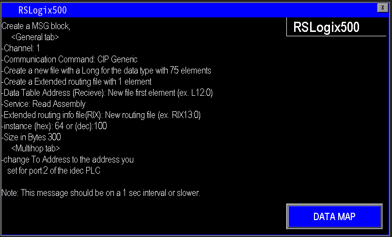
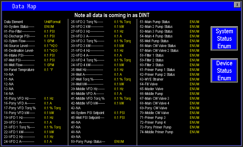
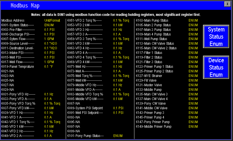
After updating the PLC with the required communication logic, the data map (Image 2.1) shows each populated tag and its meaning. Configure your RSLogix500 program to reference these data elements.
Note: All mapped data values are provided as DINTs.
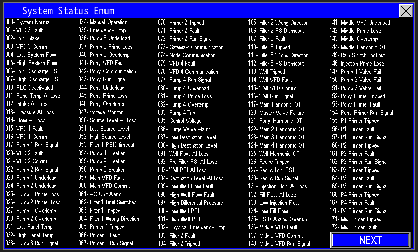
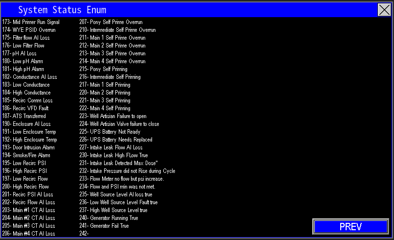
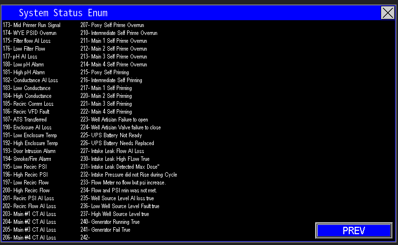
¶ View System Status Enum Bits (Images 2.2–2.3)
Open the System Status Enum page to view all status bits. Use the data map to identify the specific bits required and target those bits within your RSLogix/Studio 500 ladder logic to integrate and control the system.
|
|
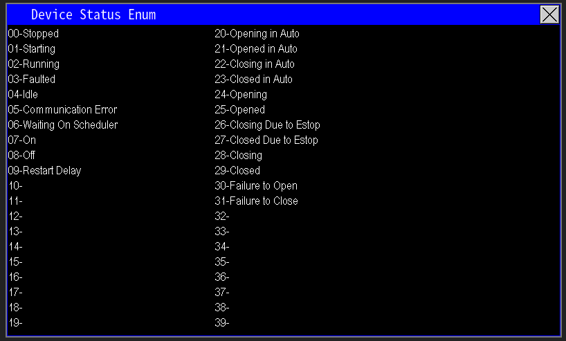
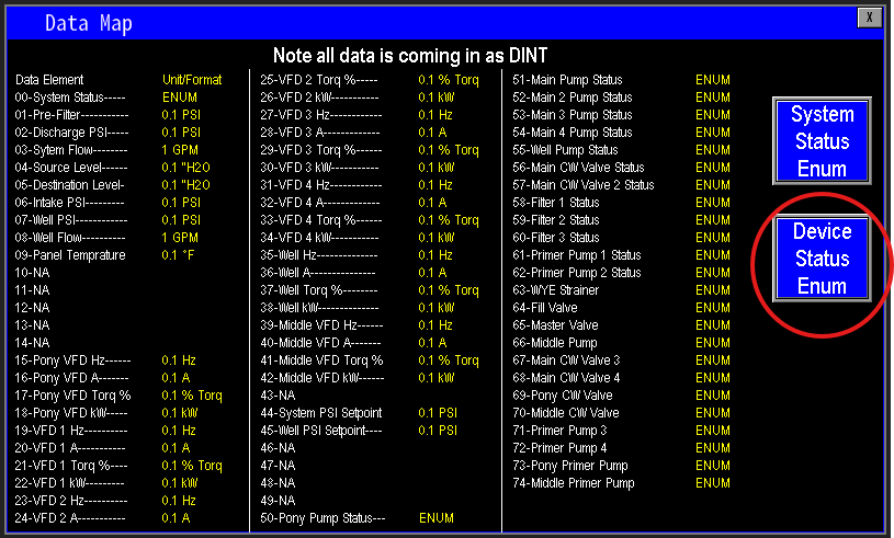
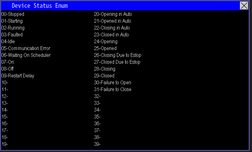
¶ Device Status Enum Bits (Image 2.4)
Open the Device Status Enum screen to view all device status bits. Identify the specific bits required for your application and reference them in your ladder logic to integrate device-level status into your control program.
¶ Studio5000
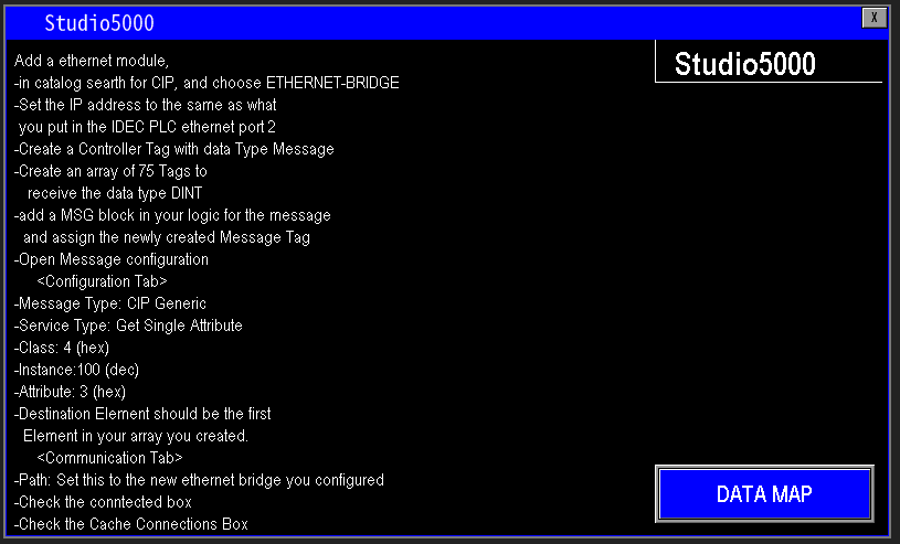
To configure Studio 5000 communications with the Omnia panel, click "Studio5000" (Image 2.5). Follow the on‑screen instructions to import the tag/address mapping and implement the required logic in your Studio 5000 project.
Implement the Studio 5000 logic as shown in Image 2.6, following the provided instruction sequence to map and exchange tags with the Omnia panel.
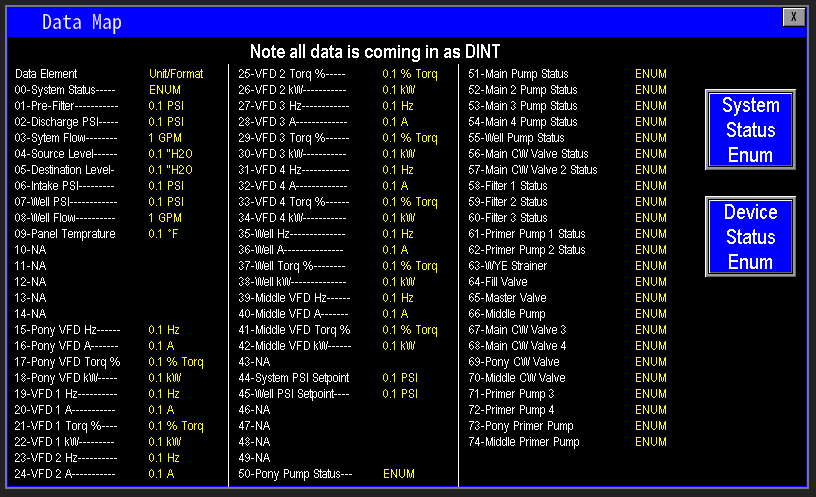
After updating the Studio 5000 project with the required communication settings and ladder logic, consult the data map (Image 2.7). It lists every populated tag and its meaning—use this map to reference and target the required data elements in your program.
Note: All mapped values are provided as DINT.
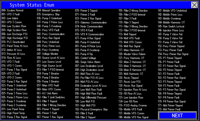
¶ System Status Enum Bits (Images 2.8–2.9)
Open the System Status Enum pages to view all status bits. Identify the specific bits required for your application and reference those bits in your Studio 5000 logic to integrate system‑level status into your control program.
|

|
¶ Device Status Enum Bits (Image 3.0)
Open the Device Status Enum screen to view all device status bits. Identify the specific bits required for your application and reference them in your control program. Map the selected bits into your logic and implement the necessary ladder/function block code to monitor and respond to those device states.
¶ Modbus TCP
Click "Modbus TCP" (Image 3.1) to open the Modbus TCP configuration and mapping interface. This screen provides the register mappings, function codes, and network settings required to expose Omnia tags over Modbus TCP for SCADA or other Modbus masters. Configure the IP/port, unit ID, and mapping per your SCADA requirements, then apply and test communications.
Once the Modbus TCP configuration and required logic are in place, consult the data map (Image 3.2) for the populated registers and their meanings. Use those Modbus addresses in your SCADA or PLC program to read/write the required values.
Note: All mapped data is provided as DINT.
¶ System Status Enum Bits (Images 3.4–3.5)
Open the System Status Enum pages to view all status bits and their meanings. Identify the specific bits your SCADA or controller needs, then reference those bits in your program to monitor and respond to system-level conditions.

|
|
¶ Device Status Enum Bits (Image 3.6)
Open the Device Status Enum screen to view all device status bits and their definitions. Identify the bits required for your application, then map and reference them in your control or SCADA program to monitor and respond to device-level conditions.