¶ Source Level Settings
The source level transmitter measures the level of the water supply feeding the pump station (image 1.1). These settings configure the transmitter to ensure accurate level detection and include protection parameters to prevent damage to the pumps. Proper setup helps maintain reliable operation and safeguards the system from operating under low or excessive water levels.
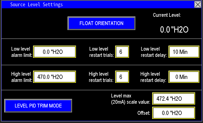
¶ Float orientation
The float orientation setting (image 1.2) determines how the float switches are installed within the tank or water supply system. These floats are digital inputs used as backup protection in case the level transmitter malfunctions or fails. Proper configuration of the float orientation provides an additional layer of control, ensuring the pumps operate safely and prevent overfilling or running dry if the primary level measurement system is compromised.

Selecting the float orientation allows the PLC to interpret the float switch signals correctly. Different float switches are configured as normally open (floating) or normally closed (hanging), and choosing the correct setting is essential for proper operation.
- Floating (image 1.3): Typically refers to float switches that open or close contacts as the float rises or falls, used in certain installation orientations.
- Hanging (image 1.4): Refers to switches that hang from a fixed point and change state based on water level.
Identify the type of float switches installed at the station, then select the appropriate configuration to ensure accurate system responses and protect the pump operation.

|

|
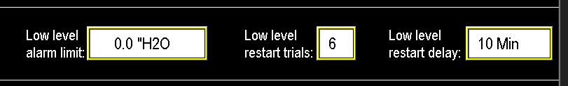
¶ Low level alarm limit, restarts, and delay
The low level alarm setting (Image 1.5) prevents the pump from running when water levels are too low, protecting the system from running dry and damaging seals. When the water level reaches the low alarm limit, the alarm activates and the pump halts. The alarm remains active until water levels rise above the low level threshold.
Once water levels recover, the restart delay timer begins (e.g., 10 minutes). If water level stays above the low alarm limit during this entire delay, the pump will restart. This process can repeat for the configured number of restart trials (e.g., 6 times). If the pump fails to maintain adequate water levels after exhausting the restart attempts (e.g., hitting the 7th low level), the system will trigger a hard fault, requiring manual intervention to investigate and resolve the underlying issue causing the water shortage.
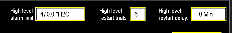
¶ High level alarm limit, restarts, and delay
The high level alarm operates similarly to the low level, but it does not cause a fault in the station itself (Image 1.6). If the station includes a well pump, exceeding the high level alarm will fault the well pump to prevent overfilling. The high level alarm remains active until water levels drop back into the normal operating range.
Once the water level falls below the high alarm threshold, the restart delay timer (e.g., 10 minutes) begins. During this period, if the level stays below the high alarm limit, the timer continues counting. After the delay expires, the alarm resets, and the well pump is allowed to operate again.
This process can repeat up to the configured number of restart trials (e.g., 6 attempts). If the high level occurs again after all retries, the alarm will remain active and will not reset until manually addressed. This indicates a potential issue with overfilling or source control that needs site inspection, and during this fault condition, the well pump will also be faulted to prevent further overfilling.
¶ Transmitter scaling and offset
To ensure the level readings are accurate, set the Level Max (20mA) scale value to match the maximum level range specified on the transmitter (image 1.7). Check the transmitter's maximum rating in its documentation or directly at the device, then input that value into the Level Max (20mA) setting.
The offset represents the distance between the bottom of the tank and the bottom of the transmitter. This adjustment allows the transmitter to be installed above the tank bottom without being affected by mud or debris, while still accurately measuring the water level — including the space below the transmitter.
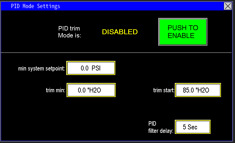
¶ Level PID trim mode
This feature enables the tank level to influence pump operation, helping to extend the water cycle by adjusting pump speed based on water level (image 1.8). Normally, the pumps operate under pressure PID control until they sleep or fault. When enabled, Level PID trim adjusts the pump speed proportionally to the level in the tank: as the water level drops, the PLC reduces the pump’s pressure setpoint (Image 1.9), allowing the pump to run at a lower pressure.
This adjustment helps the zone receive water for a longer period, albeit at a lower pressure, before the system faults or goes to sleep. For detailed operation, refer to the PID Trim Mode section under Discharge Pressure settings, which explains how level-based adjustments influence pressure control.

|
|