¶ Panel Temperature Settings
Monitoring panel temperature is essential to maintain reliable operation of electrical components (image 1.1). Extreme heat or cold accelerates component degradation and can cause malfunctions that affect communications and overall panel performance. The PLC includes a dedicated analog input for the panel temperature sensor—use this input to monitor and alarm on out-of-range conditions to protect the equipment.
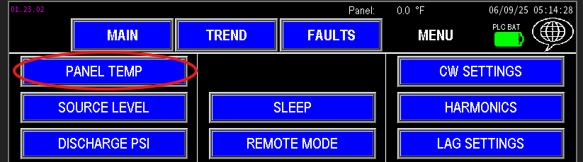
¶ Temperature settings screen
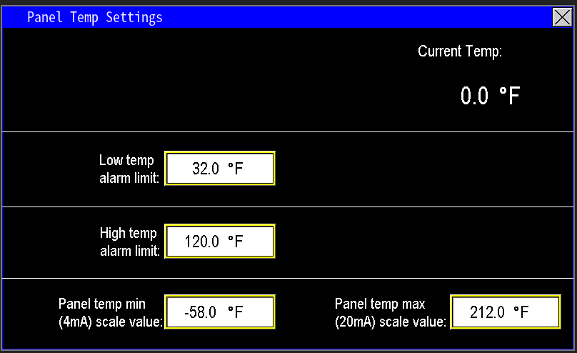
The panel screen provides fields to configure the temperature monitoring parameters (image 1.2). In the top-right corner you will see the live panel temperature readout. Use the configuration fields on this screen to set alarm thresholds, scaling, and any delays required for alarm logic.
¶ Low temp and high temp alarm limit
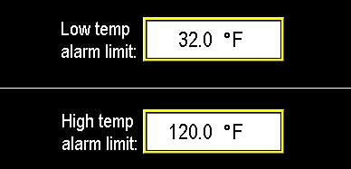
Set the low and high temperature alarm limits (image 1.3) to reflect the panel’s optimal operating range and the environmental conditions it is exposed to. For example, in the illustration the panel will trigger a low‑temperature alarm below 32°F and a high‑temperature alarm above 120°F. These alarms do not power the panel on or off; they notify operators and protect internal components by prompting corrective action when temperatures move outside the defined safe range.
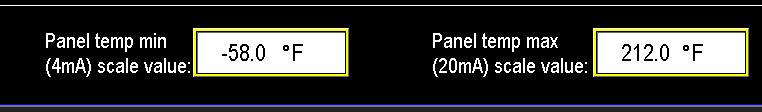
¶ Transmitter scaling
If the RTD or temperature transmitter is replaced with a unit that has a different span, update the PLC scaling to match the new device. Enter the transmitter’s minimum temperature (corresponding to 4 mA) into Panel Temp Min (4 mA) and the transmitter’s maximum temperature (corresponding to 20 mA) into Panel Temp Max (20 mA). This ensures the HMI displays correct temperature readings (image 1.4).