¶ Leak Flow Meter
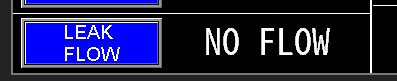
Leak flow meters are used on pump stations with primer or suction lift pumps. They monitor the total flow of water recirculating back into the intake side of the pumps, which helps keep the intake system primed. An abnormally high Leak flow indicates a leak at the foot valve or intake column. The system may cycle off and on to maintain discharge pressure, alerting operators to potential leak issues.
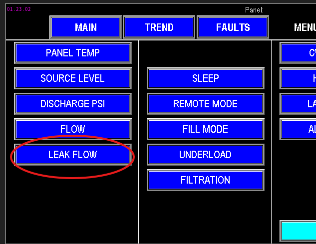
To configure leak flow monitoring, access the Leak Flow Settings via the Main screen (Image 1.1) or the menu screen (Image 1.2).
|
|
¶ Leak Flow settings
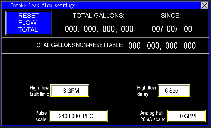
The values entered into the Leak Flow Settings screen (image 1.3) are the parameters the PLC will use to monitor and control the leak detection and prevention functions. These settings determine how the system detects excessive recirculating flow and triggers appropriate responses, such as cycling the pumps or generating alarms. Proper configuration ensures accurate leak detection and effective pump operation.
¶ Leak Flow Data
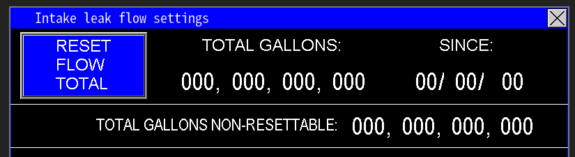
At the top of the screen (image 1.4) is all the data that the PLC is collecting from the Leak flow meter itself. This is the total gallons the Leak flow meter has registered getting put back into the intake side of the pumps. The “since” is the date that updates when the “Reset Flow Total” is pressed. When “Reset Flow Total” is pressed, the “since” will update to the current date the HMI is set at, and will zero out the Total Gallons totalizer.
The Total Gallons Non-Resettable totalizer cannot be reset, but shows how many total gallons the station has pumped in its lifetime.
¶ High Flow fault limit and delay
The High flow limits are to help suggest to the PLC that there is a problem with intake of the pump station that needs resolved (image 1.5). It monitors the gpm flow amount, and a timer delay. The High flow fault will not fault the station, but it will send an alarm to signify that too much water is feeding back into the intake to keep it primed. In the example below, the High flow fault will alarm when the flow meter reads 3 gpm or more within 6 secs.

¶ Pulse Scale and Analog Full 20mA scale
The flow meter used for the Leak flow meter works the same as all other flow meters. The difference is the flow meter is trying to detect a smaller amount of water as in a few gallons per minute vs hundreds or thousand gallons per minute. Ensure when replacing, that the flow meter going back into the station is capable of reading thousands of pulses per second vs hundreds.
Next, zero the mA Scale—this activates the pulse measurement mode. If the mA scale is not zeroed, pulse readings will not function correctly. Once configured, the system converts incoming pulses into flow rates, displaying the flow in GPM on the main screen of the HMI (Image 1.6).
The Analog Full 20mA Scale should be set to match the maximum flow rating of the flow meter’s 20mA output. This value typically represents the highest flow the meter is rated to measure. For meters with adjustable 20mA span, verify that this scale matches the configured maximum output value on the flow meter to ensure accurate readings and proper system calibration.