¶ I/O Status
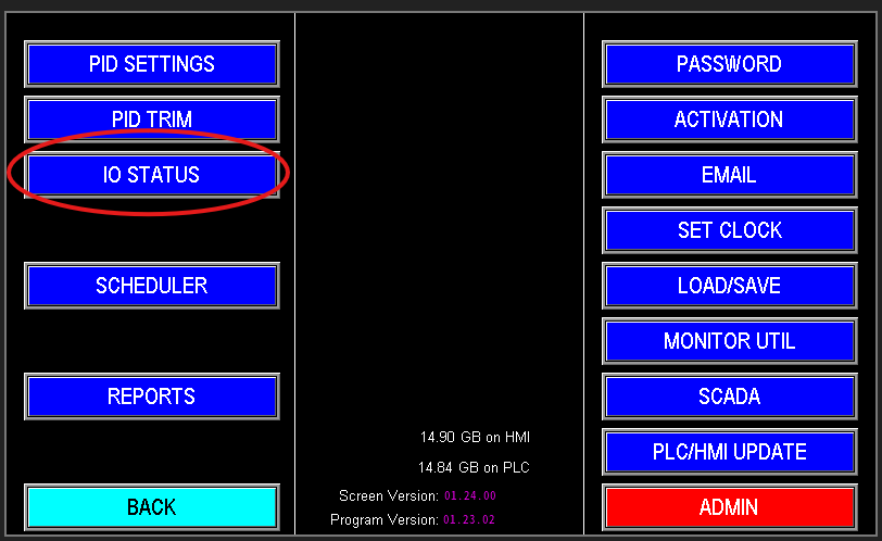
The IO Status screen displays real-time data on all inputs, outputs, and analog signals within the station. It provides an at-a-glance view of current sensor readings, valve statuses, relay states, and signal values. This makes it an invaluable tool for troubleshooting, verifying proper operation, and observing how the station responds to various conditions. If the station is acting unexpectedly or reacting oddly, the IO Status screen is the ideal place to monitor exactly what signals and signals states the system is detecting at that moment.
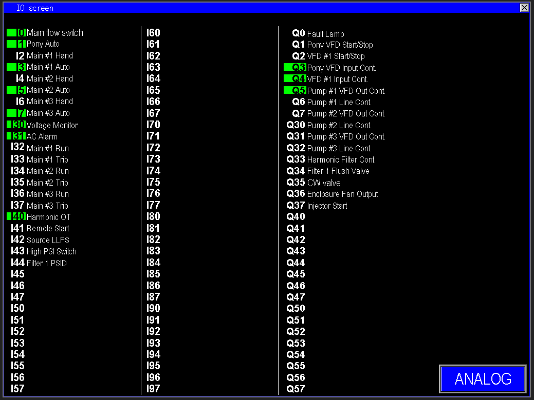
This screen lists all configured inputs and outputs for the job (image 1.2). A green indicator next to an input (e.g., I0, I1, I3, I5, I7, I30, I31, I40) shows it is actively receiving a signal, meaning it’s turned on or detects an active state.
On the output side, Q3, Q4, and Q5 are turned on and supplying power to their respective devices, such as VFD contactors. To monitor the analog signals, click on the "Analog" button located in the bottom right of the screen. This allows you to view real-time analog input and output values for precise system monitoring.
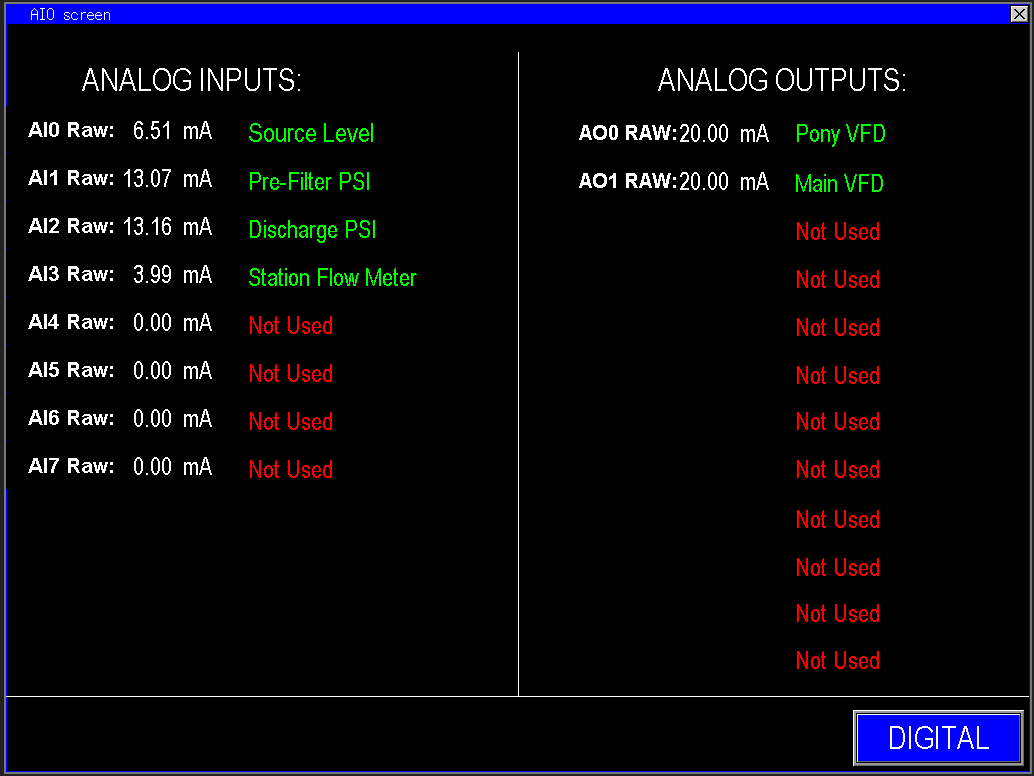
- When the bottom of the screen says “Digital” (Image 1.3), you are viewing the analog input/output signals.
- When it says “Analog” (Image 1.4), you are viewing the digital input/output signals
The PLC outputs (image 1.3) a 4–20mA control signal to the Variable Frequency Drive (VFD), which converts this current into a corresponding frequency (Hz) to regulate motor speed. At the lower end, 4mA represents the minimum operational frequency, while 20mA corresponds to the maximum setpoint. This proportional control methodology allows for precise and accurate modulation of motor speeds and device operations, ensuring smooth system performance and optimal process control. Additionally, these analog outputs can represent positional signals for modulating valves or transmit sensor readings to a SCADA system for comprehensive remote monitoring and control.